- 5 VNominal supply
- ≈ 120 mWTypical power (estimated)
- 31 × 31 mmBoard size
- 28 sCold-start time to first fix
Overview
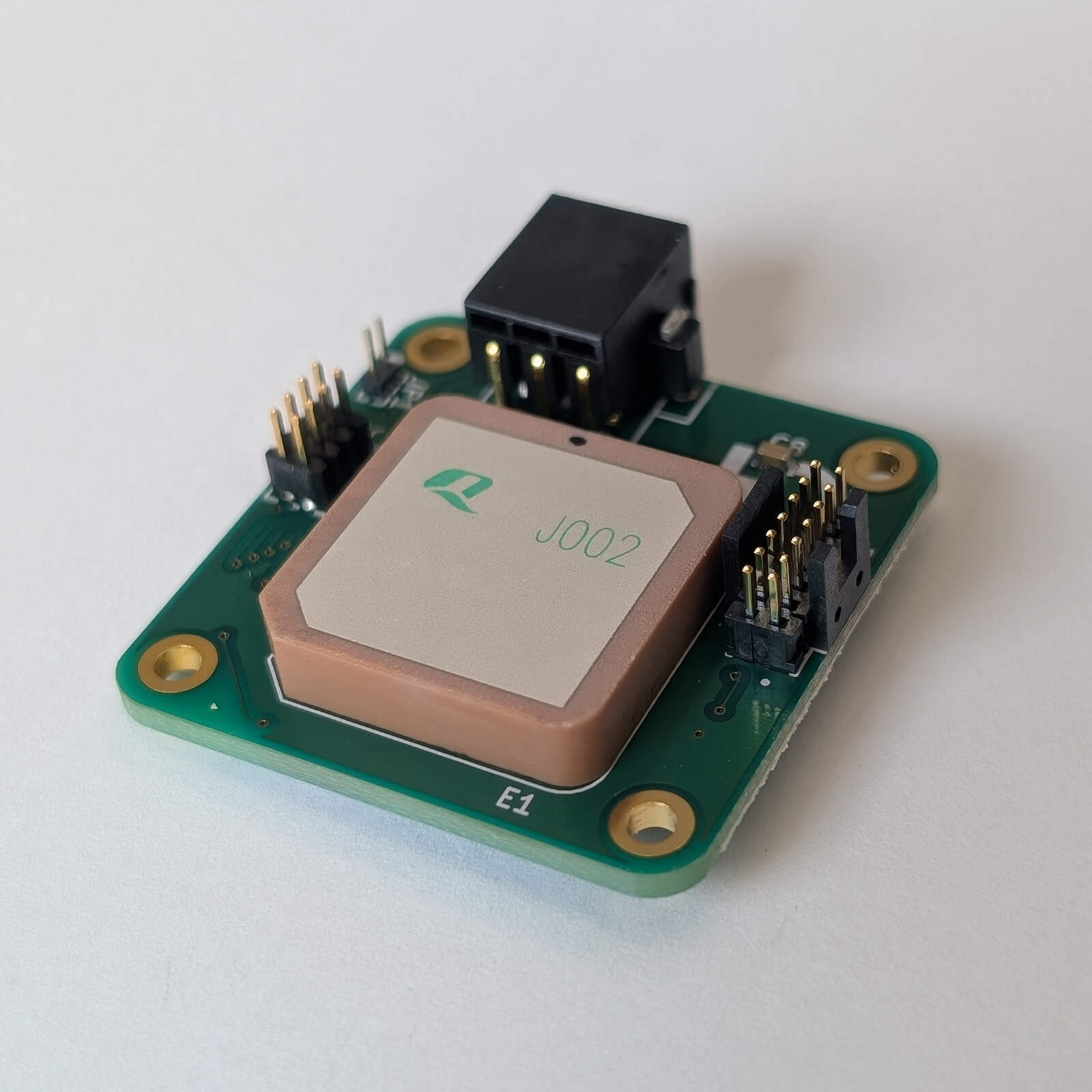
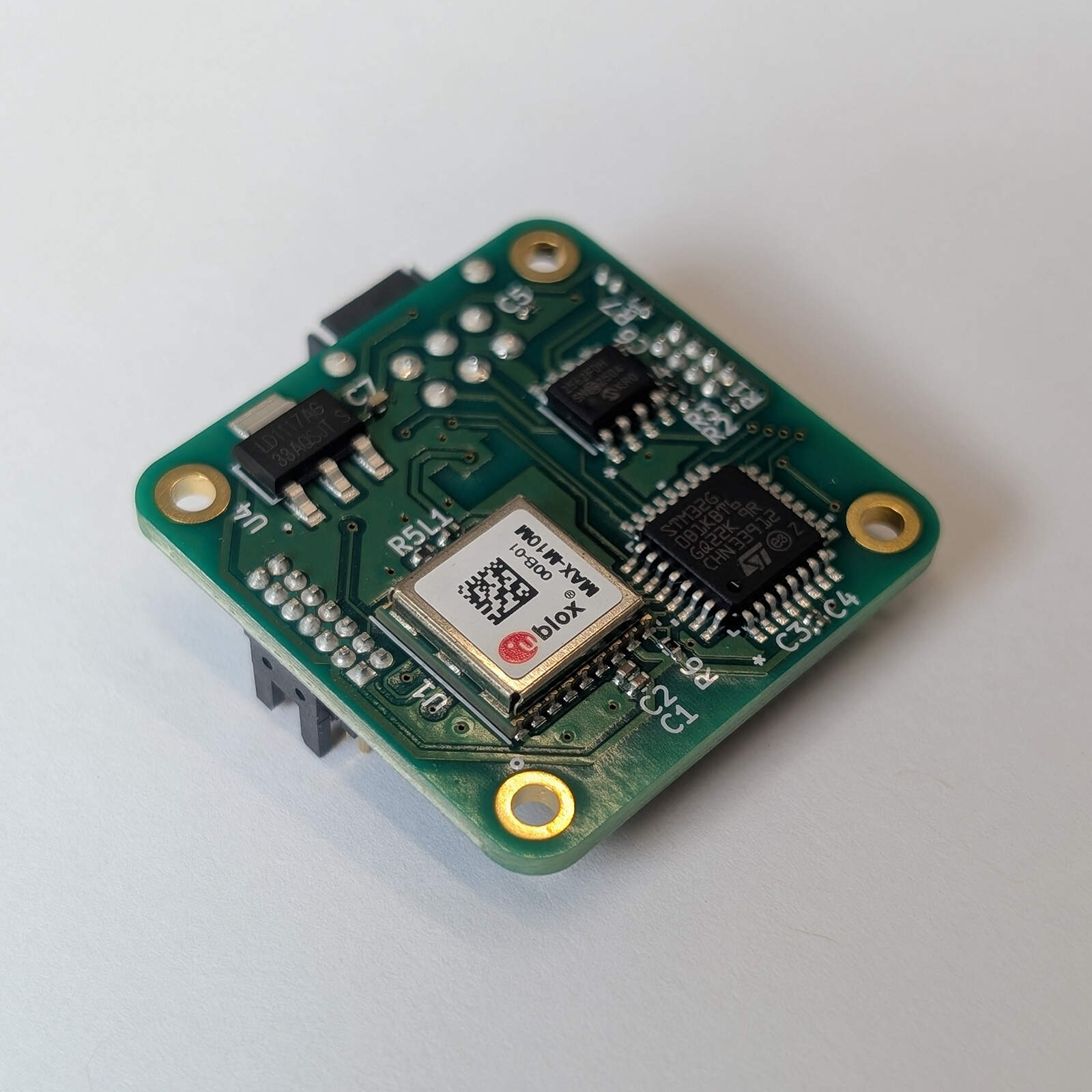
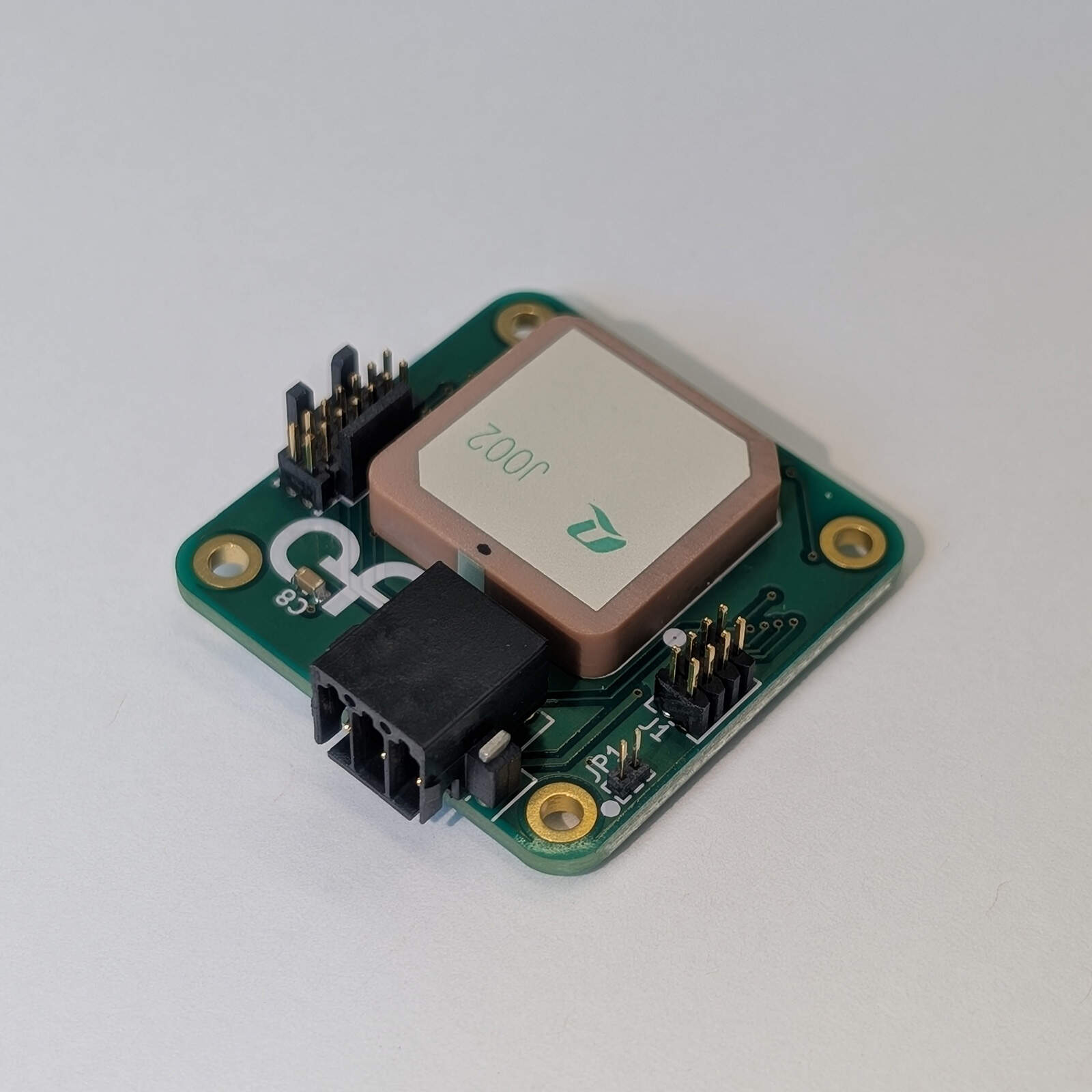
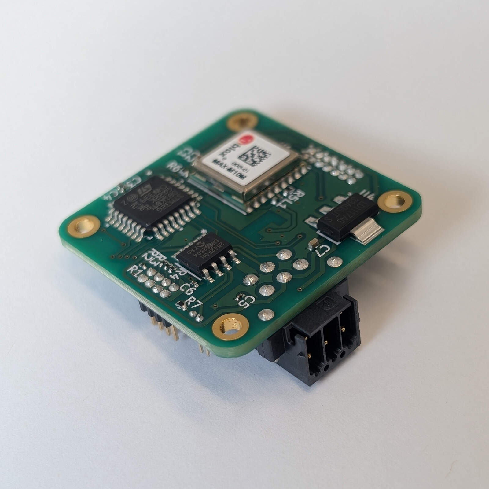
The UBXGNSS is a compact, self-contained GNSS receiver board that provides reliable position and navigation data to a UAV flight controller over a DroneCAN (UAVCAN) interface. It integrates a ceramic patch antenna, a ublox MAXM10M00B GNSS receiver module, an STM32G0B1KBT6 microcontroller and an MCP2562FD CAN transceiver on a single 31 × 31 mm board.
The MAXM10M00B receives GPS and Galileo signals (with QZSS and SBAS) from the on-board antenna and sends the resulting navigation messages to the microcontroller over an I²C interface. The STM32G0B1KBT6 processes this data, packages the relevant navigation information into DroneCAN messages and transmits them to the flight controller over the board’s FDCAN bus.
Key features
- Concurrent GPS and Galileo reception, with QZSS and SBAS (ublox MAXM10M00B)
- On-board ceramic patch GNSS antenna, 1575.42–1602 MHz
- DroneCAN (UAVCAN) communication over classic CAN at 1 Mbit/s (FDCAN peripheral, MCP2562FD transceiver), with selectable 120 Ω bus termination
- STM32G0B1KBT6 microcontroller with 128 KB flash
- 144 KB SRAM (128 KB with hardware parity check)
- Position output at 10 Hz, receiver configured for airborne use
- Node ID selected by header jumpers (16 to 31), or any value from 1 to 127 set over CAN
- STDC14 debug and programming port for the ST-LINK-V3MINIE
- Compact 31 × 31 mm board
Technical specifications
| Parameter | Value | Unit |
|---|---|---|
| Electrical | ||
| Nominal supply voltage | 5 | V |
| Minimum operating voltage | 4.5 | V |
| Maximum operating voltage | 5.5 | V |
| Typical power consumption (estimated) | ≈ 120 | mW |
| Typical input current (estimated) | ≈ 24 | mA |
| Performance | ||
| Maximum altitude | 50 | km |
| Maximum velocity | 500 | m/s |
| Velocity accuracy | 0.05 | m/s |
| Dynamic heading accuracy | 0.3 | ° |
| Horizontal position accuracy (CEP) | 1.5 | m |
| Position update rate | 10 | Hz |
| Time to first fix (cold start) | 28 | s |
| Time to first fix (hot start) | 1 | s |
| Tracking sensitivity | -165 | dBm |
| Antenna | ||
| Antenna frequency range | 1575.42–1602 | MHz |
| Antenna gain (maximum) | 3.0 | dBi |
| Antenna polarization | RHCP | |
| Environmental | ||
| Operating temperature | -40 to +85 | °C |
Power and current are estimates from the typical supply currents given in the data sheets of the components (the 3.3 V rail loads, the regulator quiescent current and the CAN transceiver) at 5 V with the receiver tracking satellites; they have not been measured. Each fitted ID jumper adds about 0.33 mA.
Altitude and velocity limits assume the airborne 4 g platform model, which the firmware selects at start-up. Position accuracy, velocity and heading accuracy, start-up times and sensitivity are the ublox MAXM10M00B figures for GPS and Galileo (CEP at 50 % over 24 hours, static, -130 dBm; velocity and heading at 30 m/s). The hot-start time applies only while the receiver stays powered: the board has no backup supply for the receiver, so a start after power-up is a cold start.
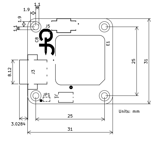
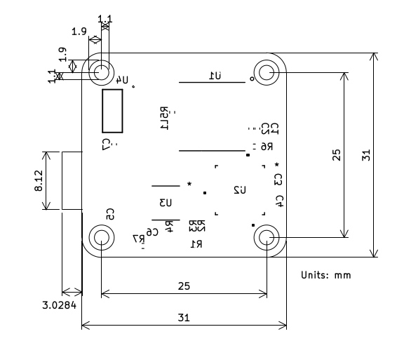
The board measures 31 × 31 mm and is 1.6 mm thick, with four M2 mounting holes (2.2 mm) on a 25 × 25 mm pattern. All dimensions in the drawings are in millimetres.
Absolute maximum ratings
Stresses beyond these values may cause permanent damage. They are estimated from the absolute maximum ratings of the board’s components (the lowest limit among the parts connected to each pin) and have not been tested on the board. The 5 V input has no reverse-polarity or over-voltage protection, and the voltage ratings of the capacitors were not assessed.
| Parameter | Min | Max | Unit | Limited by |
|---|---|---|---|---|
| Supply voltage, 5V pin (J3 pin 2) | -0.3 | 7.0 | V | MCP2562FD supply |
| Voltage on CAN_H and CAN_L (DC) | -58 | +58 | V | MCP2562FD |
| Transient on CAN_H and CAN_L (ISO 7637) | -150 | +100 | V | MCP2562FD |
| ESD on CAN_H and CAN_L (HBM) | ±8 | kV | MCP2562FD | |
| Voltage on J1 and J5 signal pins | -0.3 | 3.6 | V | STM32G0B1KBT6 (3.3 V I/O) |
| Storage temperature | -40 | +85 | °C | u-blox MAX-M10M-00B |
The receiver module is supplied from the on-board 3.3 V rail. Its own limits (supply -0.3 to 6 V, RF input +15 dBm, operating and storage temperature -40 to +85 °C) apply inside the board.
Interfaces and connectors
| Ref. | Function | Connector / mating part |
|---|---|---|
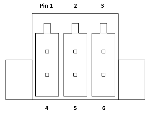
| J3 | Power and CAN data bus | Mating part: Phoenix Contact 1027605 |
| JP1 | 120 Ω CAN termination | 1 mm pitch jumper |
| J5 | Debug and firmware programming | 14-pin STDC14 Cortex ribbon cable |
| J1 | Hardware ID pins | 8-pin header, 1.27 mm pitch |
Power and CAN Data Bus (J3)
J3 carries power input and the CAN bus. The mating connector is the Phoenix Contact 1027605.
| Pin | Net | Type |
|---|---|---|
| 1 | NC | Not connected |
| 2 | 5V | Power input |
| 3 | GND | Power input |
| 4 | GND | Power input |
| 5 | CAN_H | I/O |
| 6 | CAN_L | I/O |
120 Ω Termination Jumper (JP1)
Fitting a jumper on JP1 connects a 120 Ω termination across the CAN bus. Jumper pitch: 1 mm.
STDC14 Debug Connector (J5)
J5 is designed for use with the ST-LINK-V3MINIE and can be used to debug the board or load firmware onto the receiver. Mating part: 14-pin STDC14 Cortex ribbon cable.
| Pin | Signal |
|---|---|
| 3 | +3.3V |
| 4 | SWDIO |
| 5, 7, 11 | GND |
| 6 | SWCLK |
| 12 | NRST |
| 1, 2, 8, 9, 10, 13, 14 | Not connected |
Hardware ID Pins (J1)
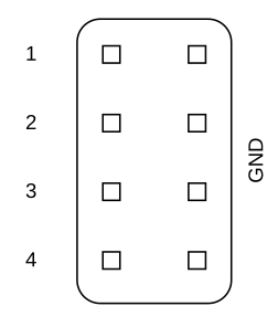
J1 is an 8-pin header (1.27 mm pitch) with four ID rows. Each row has an ID pin and, beside it, a ground pin. Fitting a jumper across a row sets that bit of the hardware ID to 1; an open row reads 0. The node ID is 16 plus this 4-bit number, so the jumpers select 16 to 31, and the node ID is 16 with no jumpers fitted. The pins are read at start-up only: reset or power-cycle the board after changing a jumper. Each fitted jumper draws about 0.33 mA. An ID from 1 to 127 can also be stored over CAN; a stored ID takes priority over the jumpers.
| Row 1 (bit 0) | Row 2 (bit 1) | Row 3 (bit 2) | Row 4 (bit 3) | Node ID (decimal) | Node ID (hex) |
|---|---|---|---|---|---|
| 0 | 0 | 0 | 0 | 16 | 0x10 |
| 1 | 0 | 0 | 0 | 17 | 0x11 |
| 0 | 1 | 0 | 0 | 18 | 0x12 |
| 1 | 0 | 1 | 0 | 21 | 0x15 |
| 1 | 1 | 1 | 1 | 31 | 0x1F |
Software and firmware
This board is a DroneCAN (UAVCAN v0) node. It uses classic CAN (CAN FD is not used) at 1 Mbit/s with 29-bit identifiers.
Node ID
Every node on a DroneCAN bus has a unique node ID from 1 to 127, which is the source address of the messages it sends. The ID is 16 plus the jumper setting, unless an ID has been stored over CAN.
To set the ID over CAN, use the standard DroneCAN parameter services (for example in the DroneCAN GUI tool): write the integer parameter NODE_ID (1 to 127) with uavcan.protocol.param.GetSet. The value is stored in flash straight away and is used after the node restarts, which can be requested with uavcan.protocol.RestartNode. Writing 0, or the ExecuteOpcode erase command, removes the stored ID so that the jumpers decide again. Values outside 0 to 127 are ignored. Writing flash stops the processor for a few tens of milliseconds, so do not change the ID while the aircraft depends on the GNSS data.
Priority
DroneCAN priorities run from 0 (highest) to 31 (lowest). The position message uses priority 16; the auxiliary and node status messages use priority 24.
Message Definitions
The board publishes the standard GNSS messages that flight controllers such as PX4 and ArduPilot use:
| Message | Type ID | Rate | Priority |
|---|---|---|---|
| uavcan.equipment.gnss.Fix2 | 1063 | 10 Hz | 16 |
| uavcan.equipment.gnss.Auxiliary | 1061 | 1 Hz | 24 |
| uavcan.protocol.NodeStatus | 341 | 1 Hz | 24 |
The board also answers the services uavcan.protocol.GetNodeInfo (name, software version, unique ID), uavcan.protocol.param.GetSet and ExecuteOpcode (node ID, see above) and uavcan.protocol.RestartNode.
Fix2 fields
| Field | Description |
|---|---|
| gnss_timestamp | UTC time of the solution in microseconds since 1970-01-01. 0 until the receiver knows the date and time. |
| gnss_time_standard | 2 (UTC), or 0 when the time is not known. |
| timestamp | Network-synchronised time. Not available, always 0. |
| latitude_deg_1e8, longitude_deg_1e8 | Signed latitude and longitude in degrees × 10⁸. |
| height_ellipsoid_mm, height_msl_mm | Height above the ellipsoid and above mean sea level, in millimetres. |
| ned_velocity | North, east and down velocity in m/s, from ground speed and course. The down component is 0. |
| sats_used | Number of satellites used in the solution. |
| status | 0 = no fix, 2 = 2D fix, 3 = 3D fix. |
| mode | 0 = single; 1 = DGPS and 2 = RTK when the receiver reports them. |
| pdop | Position dilution of precision. |
| covariance | Not provided (empty). Receivers derive accuracy from the dilution of precision in Auxiliary. |
Auxiliary fields
| Field | Description |
|---|---|
| pdop, hdop, vdop | Position, horizontal and vertical dilution of precision. |
| gdop, tdop, ndop, edop | Not provided (NaN). |
| sats_visible, sats_used | Satellites in view and satellites used in the solution. |
NodeStatus health
Having no fix is not a fault. The node status reports a fault only when the GNSS receiver is missing or silent:
| Health | Vendor status code | Meaning |
|---|---|---|
| OK | 0 | The receiver is producing solutions. |
| WARNING | 2 | The receiver has sent no solution for 3 seconds. |
| ERROR | 1 | The receiver has not answered on I²C. |
Firmware
Firmware source code and firmware binaries are published in the Ether Form Inc GitHub organization:
Resources
- Firmware source code and binaries (Ether Form Inc GitHub organization): github.com/Ether-Form-Inc
- DroneCAN specification: CAN bus transport layer
- DroneCAN message definitions: DroneCAN DSDL (uavcan)
References
[1] “4.1 CAN bus transport layer – DroneCAN,” GitHub Pages, 2025. https://dronecan.github.io/Specification/4.1_CAN_bus_transport_layer/ (accessed Sept. 9, 2026).
Request a quote or discuss your integration
Choose the inquiry type that fits. A standard bulk quote only needs a quantity and your contact details; engineering and customization inquiries need a short description of what you need.