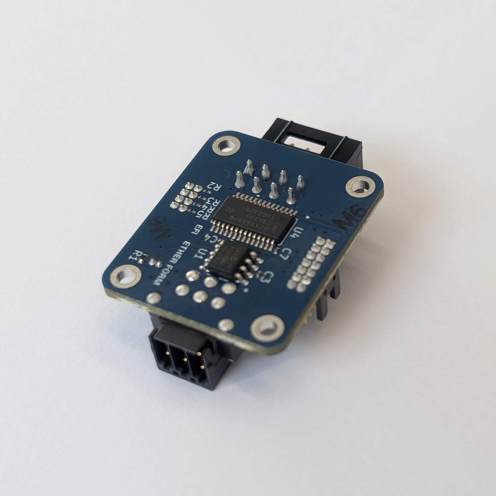
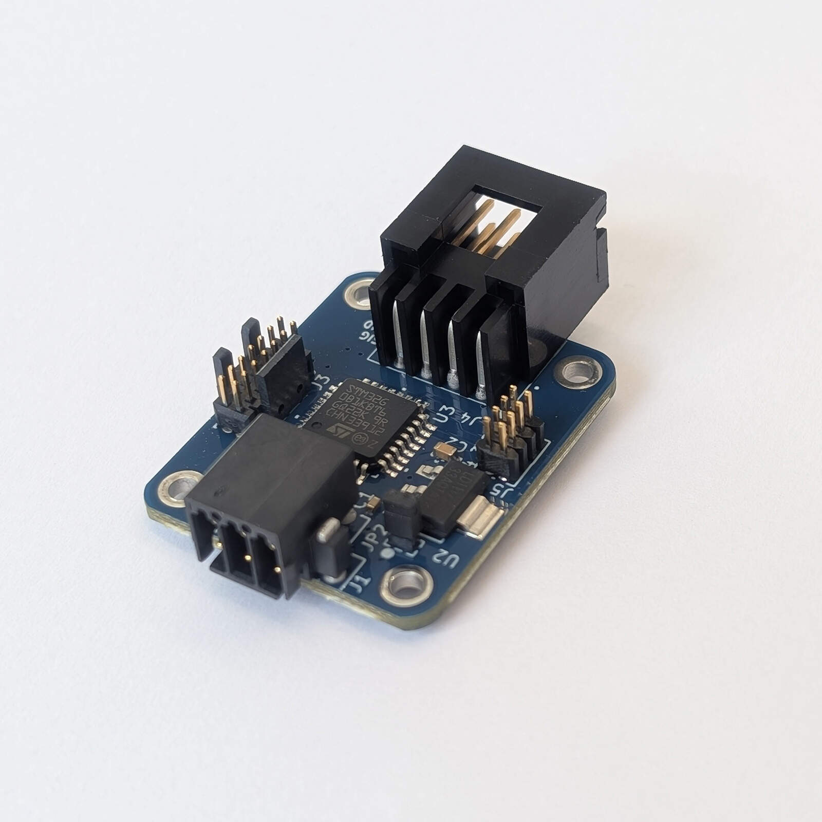
- 5 VNominal supply
- 4PWM outputs
- 31 × 26 mmBoard size
- 1 Mbit/sCAN bit rate
Overview
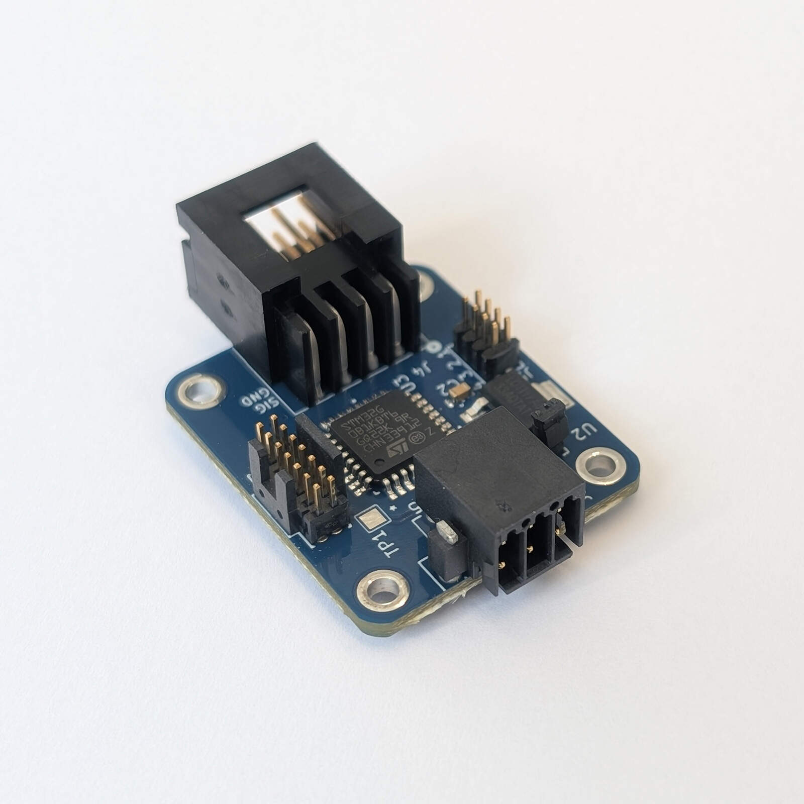
The PWM1 is a compact, self-contained PWM controller that gives a UAV flight controller four distributed servo or ESC outputs over a DroneCAN (UAVCAN) bus. Running off of 5V, the on-board microcontroller receives a flight controller’s actuator commands over the board’s CAN bus and drives up to four PWM signals. The board listens for either servo commands (uavcan.equipment.actuator.ArrayCommand) or motor commands (uavcan.equipment.esc.RawCommand), as selected by a jumper on J5, and answers only the actuator IDs assigned to it. The PWM1 is out-of-the-box compatible with all UAVCAN flight stacks including PX4.
Key features
- 4 PWM outputs from a 12-bit PCA9685 driver, 50 Hz, 3.3 V logic level
- Servo mode (ArrayCommand) or motor mode (RawCommand), selected with a jumper
- DroneCAN (UAVCAN) over classic CAN at 1 Mbit/s (FDCAN peripheral, MCP2562FD transceiver), with selectable 120 Ω bus termination
- Node ID, pulse width limits, motor timeout and PWM timing calibration programmable over CAN and stored in flash
- Actuator ID offset (0 to 7) selected with header jumpers
- STM32G0B1KBT6 Cortex-M0+ microcontroller with 128 KB flash and 144 KB SRAM
- Single 5 V supply (4.5 to 5.5 V)
- STDC14 debug and programming port for the ST-LINK-V3MINIE
- Compact 31 × 26 mm board
Technical specifications
| Parameter | Value | Unit |
|---|---|---|
| Electrical | ||
| Nominal supply voltage | 5 | V |
| Minimum operating voltage | 4.5 | V |
| Maximum operating voltage | 5.5 | V |
| Typical input current | 61.9 | mA |
| Typical power consumption | 309.5 | mW |
| PWM outputs | ||
| Number of outputs | 4 | |
| PWM frequency (after calibration) | 50 | Hz |
| Resolution (PCA9685) | 12 bit | |
| Pulse width step | ≈ 4.9 | µs |
| Pulse width range (default, programmable) | 1000–2000 | µs |
| Output logic level (push-pull) | 3.3 | V |
| Motor mode command timeout (default, programmable) | 5 | s |
| CAN bus | ||
| Bit rate | 1 | Mbit/s |
| Frame format | Classic CAN, 29-bit ID | |
| Protocol | DroneCAN (UAVCAN v0) | |
| Default node ID | 10 | |
| Bus termination | 120, selectable (JP2) | Ω |
| Environmental | ||
| Operating temperature (component rating) | -40 to +85 | °C |
The microcontroller runs at 16 MHz from its internal oscillator. The PWM period and pulse width resolution come from the PCA9685's internal oscillator and prescaler (20 ms in 4096 steps when calibrated). That oscillator is only accurate to about ±10 %, so each board should be calibrated with the PWM_PRESCALE parameter; an uncalibrated board can have a period and pulse widths off by that much. The operating temperature is the common range of the components (STM32G0B1KBT6, PCA9685PW, MCP2562FD-H and LD1117-3.3) and has not been tested on the board.
The PWM1 does not supply power to the servos or ESCs. J4 carries only the signal and ground of each channel, so the actuators need their own supply, with its ground connected to J4.
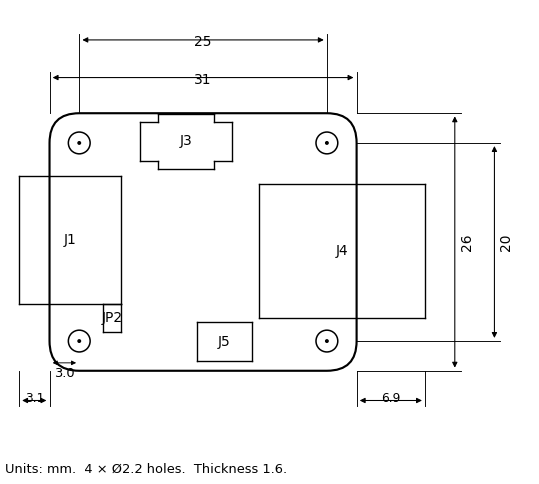
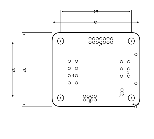
The board measures 31 × 26 mm and is 1.6 mm thick, with four M2 mounting holes (2.2 mm) on a 25 × 20 mm pattern. The J1 connector overhangs the left edge by about 3.1 mm and the J4 connector the right edge by about 6.9 mm. All dimensions in the drawings are in millimetres.
Absolute maximum ratings
Stresses beyond these values may cause permanent damage. They are estimated from the absolute maximum ratings of the board’s components (the lowest limit among the parts connected to each pin) and have not been tested on the board. The 5 V input has no reverse-polarity or over-voltage protection.
| Parameter | Min | Max | Unit | Limited by |
|---|---|---|---|---|
| Supply voltage, 5V pin (J1 pin 2) | -0.3 | 7.0 | V | MCP2562FD supply |
| Voltage on CAN_H and CAN_L (DC) | -58 | +58 | V | MCP2562FD |
| Transient on CAN_H and CAN_L (ISO 7637) | -150 | +100 | V | MCP2562FD |
| ESD on CAN_H and CAN_L (HBM) | ±8 | kV | MCP2562FD | |
| Voltage on J4, J5 and J3 signal pins | -0.3 | 3.6 | V | STM32G0B1KBT6 (3.3 V I/O) |
| Storage temperature | -40 | +85 | °C | STM32G0B1KBT6, PCA9685PW |
Interfaces and connectors
| Ref. | Function | Connector / mating part |
|---|---|---|
| J1 | Power and CAN data bus | 2 × 3 pins, 2.54 mm pitch. Mating part: Phoenix Contact 1027605 |
| JP2 | 120 Ω CAN termination | 1 mm pitch jumper |
| J3 | Debug and firmware programming | 14-pin STDC14 Cortex ribbon cable |
| J5 | Mode and actuator ID pins | 8-pin header, 1.27 mm pitch |
| J4 | PWM outputs | 2 × 4 pins, 2.54 mm pitch. Mating part: TE Connectivity 87631-3 |
Power and CAN Data Bus (J1)
J1 carries the 5 V supply input and the CAN bus. The mating connector is the Phoenix Contact 1027605.
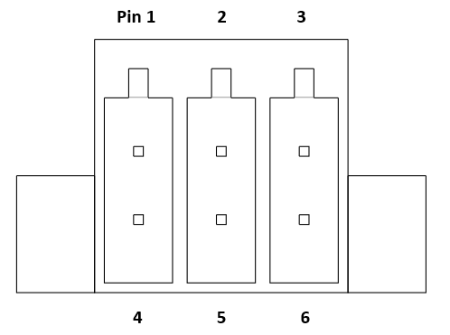
| Pin | Net | Type |
|---|---|---|
| 1 | NC | Not connected |
| 2 | 5V | Power input |
| 3 | GND | Power input |
| 4 | GND | Power input |
| 5 | CAN_H | I/O |
| 6 | CAN_L | I/O |
120 Ω Termination Jumper (JP2)
Fitting a jumper on JP2 connects a 120 Ω termination resistor across the CAN bus. Fit it only on the two nodes at the ends of the bus. Jumper pitch: 1 mm.
STDC14 Debug Connector (J3)
J3 is designed for use with the ST-LINK-V3MINIE and can be used to debug the board or load firmware onto the microcontroller. Mating part: 14-pin STDC14 Cortex ribbon cable.
| Pin | Signal |
|---|---|
| 3 | +3.3V |
| 4 | SWDIO |
| 5, 7, 11 | GND |
| 6 | SWCLK |
| 12 | NRST |
| 1, 2, 8, 9, 10, 13, 14 | Not connected |
Mode and Actuator ID Pins (J5)
J5 is an 8-pin header (1.27 mm pitch) with four rows. Each row has a signal pin (odd pin numbers 1, 3, 5, 7) beside a ground pin (even pin numbers 2, 4, 6, 8). Every signal pin has a 10 kΩ pull-up to 3.3 V, so an open row reads high and a jumper fitted across a row pulls its signal low. The board silkscreen labels the rows 4 3 2 1 from left to right.
Row 1 selects the mode: with a jumper fitted the board is in servo mode and listens for ArrayCommand, with the row open it is in motor mode and listens for RawCommand. Rows 2 to 4 form a 3-bit actuator ID offset (0 to 7) in which a fitted jumper sets the bit to 1. Output 0 answers actuator ID = offset, output 1 offset + 1, output 2 offset + 2 and output 3 offset + 3. The pins are read at start-up only, so reset or power-cycle the board after changing a jumper. This offset does not change the node ID.
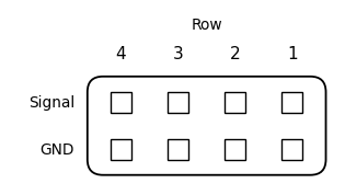
J5 pinout and function
| Row | Signal pin | GND pin | MCU pin | Function (jumper fitted = low) |
|---|---|---|---|---|
| 1 | 1 | 2 | PA8 | Mode: fitted = servo, open = motor |
| 2 | 3 | 4 | PB2 | Actuator ID offset bit 0 (LSB) |
| 3 | 5 | 6 | PB1 | Actuator ID offset bit 1 |
| 4 | 7 | 8 | PB0 | Actuator ID offset bit 2 (MSB) |
Example J5 settings (1 = jumper fitted; row 1 is the mode, rows 2 to 4 are offset bits 0 to 2)
| Row 1 | Row 2 | Row 3 | Row 4 | Mode | Offset | Actuator IDs |
|---|---|---|---|---|---|---|
| 0 | 0 | 0 | 0 | Motor | 0 | 0 to 3 |
| 1 | 0 | 0 | 0 | Servo | 0 | 0 to 3 |
| 0 | 1 | 0 | 0 | Motor | 1 | 1 to 4 |
| 1 | 1 | 1 | 0 | Servo | 3 | 3 to 6 |
| 1 | 1 | 1 | 1 | Servo | 7 | 7 to 10 |
PWM Outputs (J4)
J4 is an 8-pin header with four signal and ground pairs, one pair per PWM output. The signals are 3.3 V push-pull logic from the PCA9685. J4 has no power pin: the servo or ESC supply must come from elsewhere, with its ground connected to J4. The PWM signals are also wired to analog inputs on the microcontroller, which the current firmware does not use.
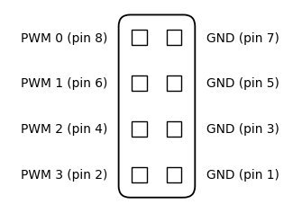
| Pin | Net | Actuator ID |
|---|---|---|
| 1, 3, 5, 7 | GND | |
| 8 | PWM 0 | offset + 0 |
| 6 | PWM 1 | offset + 1 |
| 4 | PWM 2 | offset + 2 |
| 2 | PWM 3 | offset + 3 |
Software and firmware
This board is a DroneCAN (UAVCAN v0) node. It uses classic CAN (CAN FD is not used) at 1 Mbit/s with 29-bit identifiers and accepts extended frames only.
Node ID
Every node on a DroneCAN bus has a unique node ID from 1 to 127, which is the source address of the messages it sends. The J5 jumpers select the mode and actuator IDs, not the node ID, so the node ID is 10 unless a different ID has been stored over CAN. Give each board on the same bus its own node ID.
To set the ID over CAN, use the standard DroneCAN parameter services (for example in the DroneCAN GUI tool): write the integer parameter NODE_ID (1 to 127) with uavcan.protocol.param.GetSet. The value is stored in flash straight away and is used after the node restarts, which can be requested with uavcan.protocol.RestartNode. Writing 0 removes the stored ID so that the default of 10 is used again, and the ExecuteOpcode erase command removes the stored ID, pulse width limits and motor timeout. Values outside 0 to 127 are ignored. Writing flash stops the processor for a few tens of milliseconds, so do not change the ID while the actuators are in use.
Priority
DroneCAN priorities run from 0 (highest) to 31 (lowest). The node’s own messages (NodeStatus) use priority 1 in motor mode and priority 20 in servo mode.
Servo Mode (ArrayCommand)
With the J5 row 1 jumper fitted, the board subscribes to uavcan.equipment.actuator.ArrayCommand (type ID 1010). Each Command in the array whose actuator_id is between the actuator ID offset and offset + 3 updates the matching output; other entries are ignored. Only command types UNITLESS and PWM are used, and other types are ignored.
| command_type | Value | Pulse width |
|---|---|---|
| COMMAND_TYPE_PWM | 4 | command_value is the pulse width in µs, limited to the servo minimum and maximum |
| COMMAND_TYPE_UNITLESS | 0 | command_value from -1 to +1 maps linearly from the servo minimum to the servo maximum pulse width (default 1000–2000 µs); values outside the range are limited |
Motor Mode (RawCommand)
With the J5 row 1 jumper open, the board subscribes to uavcan.equipment.esc.RawCommand (type ID 1030). The command array is indexed by actuator ID: the board uses entries offset to offset + 3 (those present in the message) for outputs 0 to 3. The valid range is 0 to 8191 and maps linearly from the motor minimum pulse width (0) towards the motor maximum (8192 would be full scale); the defaults are 1000 µs and 2000 µs. Negative values are not supported, because there is no meaningful PWM for them, and are treated as 0 (1000 µs). If no RawCommand message is received for the motor timeout (5 seconds by default), the outputs are switched off.
Programmable Limits and Timeout
The limits that scale the commands, and the motor mode timeout, are programmable over CAN as integer parameters (uavcan.protocol.param.GetSet; microseconds for the pulse width limits and milliseconds for the timeout), for example from the DroneCAN GUI tool or the can_pwm_param.py script supplied with the firmware. They are stored in flash, take effect immediately and are kept across restarts. Writing 0 to a parameter, or erasing, restores its default. The pulse width limits must be 1 to 20000. The timeout must be 100 to 60000 ms, the timeout action 0 or 1, the prescale 3 to 255, and the arming time 100 to 10000 ms. A change that would leave an output with a maximum that is not above its minimum is ignored, so when moving a range up, set the maximum first. Servo commands of type PWM are also limited to the servo range, so a pulse width outside it is clamped to the minimum or maximum.
| Parameter | Default | Used for |
|---|---|---|
| SERVO_MIN_US_0 to _3 | 1000 | UNITLESS command -1; lower limit of PWM commands |
| SERVO_MAX_US_0 to _3 | 2000 | UNITLESS command +1; upper limit of PWM commands |
| MOTOR_MIN_US_0 to _3 | 1000 | RawCommand 0 |
| MOTOR_MAX_US_0 to _3 | 2000 | RawCommand full scale |
| MOTOR_TIMEOUT_MS | 5000 | Motor mode command timeout (ms) |
| MOTOR_TIMEOUT_ACTION | 0 | What the timeout does: 0 switches the outputs off, 1 holds the minimum pulse width (zero throttle) |
| PWM_PRESCALE | 121 | PCA9685 PRE_SCALE register; sets the PWM period (calibration) |
| MOTOR_ARM_MS | 0 | Motor mode start-up arming time (ms); 0 = off. Applies at the next start |
Bench measurement. Three parameters that are not stored let the board time its own PWM outputs: writing 1 to 4 to PWM_MEASURE times output 0 to 3 (it reads back 0 none yet, 1 busy, 2 done, 3 failed or refused), and PWM_PERIOD_US and PWM_HIGH_US hold the last period and idle pulse width in µs. A measurement drives the 1000 µs idle pulse on that output for about a second, so the board refuses it once it has received a command since it started, or while the PCA9685 is not answering. It is used to calibrate PWM_PRESCALE at bring-up.
Calibrating the PWM timing. The period is 4096 × (PWM_PRESCALE + 1) divided by the PCA9685 oscillator frequency, which is 20 ms at the default of 121 only if the oscillator is exactly 25 MHz. Measure the period of an output (for example with an oscilloscope while the board is sending a motor command of 0) with the default prescale and set PWM_PRESCALE to round(122 × 20000 / measured period in µs) – 1. A board measured at 18.6 ms needs 130. The change applies at once, with a pause of about a millisecond in the outputs.
Messages and Services
| Message / service | Type ID | Direction | Notes |
|---|---|---|---|
| uavcan.equipment.actuator.ArrayCommand | 1010 | Subscribed | Servo mode only |
| uavcan.equipment.esc.RawCommand | 1030 | Subscribed | Motor mode only |
| uavcan.protocol.NodeStatus | 341 | Published, 1 Hz | |
| uavcan.protocol.GetNodeInfo | 1 | Service | Name "CAN to PWM", software version and git commit, hardware version 2 (Rev B), chip unique ID |
| uavcan.protocol.param.GetSet | 11 | Service | NODE_ID, limits, timeout |
| uavcan.protocol.param.ExecuteOpcode | 10 | Service | Erase all stored settings |
| uavcan.protocol.RestartNode | 5 | Service | Applies a new node ID |
| etherform.Echo | 106 | Service | Echoes up to 6 bytes (link test) |
Output Behavior
Many ESCs have to see the zero throttle pulse (1000 µs) once before they arm, so an ESC will not arm if the motor minimum pulse width is raised above it. If MOTOR_ARM_MS is set, the board in motor mode holds all four outputs at 1000 µs for that long after power-up so the ESCs can arm, then idles them at the configured minimum pulse width until commands arrive. RawCommand messages received during the arming time are ignored. Servo mode does not arm.
After power-up the outputs stay low (0 % duty) until the first command for that output arrives.
In motor mode, if no RawCommand message is received for the motor timeout (5 seconds by default, programmable), all four PWM signals are switched off (held low), or, if MOTOR_TIMEOUT_ACTION is 1, held at the minimum pulse width (zero throttle) so an ESC stays armed. They resume with the next RawCommand. Any RawCommand message restarts the timer, whether or not it contains entries for this board. In servo mode there is no timeout: each output keeps its last pulse width, so arrange failsafe behavior in the flight controller or the actuator.
Fault Reporting
If the PCA9685 stops answering on the I²C bus, the board reports it in NodeStatus, stops writing to it, and every second tries to re-initialize it. When it answers again the health returns to OK and the outputs are restored to their last commanded state. After a CAN bus-off the board restarts its CAN controller every 100 ms until it rejoins the bus.
| Health | Vendor status code | Meaning |
|---|---|---|
| OK | 0 | The PCA9685 is answering. |
| ERROR | 1 | The PCA9685 did not answer on the I²C bus; the PWM outputs may not follow commands. |
Firmware
The PWM1 ships pre-programmed with its firmware and is ready to use out of the box. This section is only needed by developers and by anyone who wants to update the firmware.
Firmware source code and firmware binaries are published in the Ether Form Inc GitHub organization:
Programming the Board
A new board is set up in one step with tools/bring_up.py: it erases the flash, programs the firmware, runs a CAN transceiver self-test, calibrates the PWM timing (PWM_PRESCALE) against the MCU’s timer, checks all four outputs, and records the result in a log file. To update the firmware on a configured board, connect an ST-LINK-V3MINIE to J3 (STDC14) and run make flash in the firmware repository. This runs tools/flash_and_check.py, which programs and verifies the firmware over SWD with OpenOCD, resets the board and then checks over CAN that the node answers GetNodeInfo with health OK, and prints PASS or FAIL. The node ID, pulse width limits and motor timeout stored in flash are kept when the firmware is updated unless the script is asked to clear them.
The firmware version (major.minor, with the git commit it was built from) and the hardware version (the board revision as a number: Rev A is 1, Rev B is 2) are reported by GetNodeInfo and is also stored in flash right after the vector table, so it can be read over SWD without a CAN connection. flash_and_check.py shows it before and after programming and checks that the board reports the version that was programmed.
Configuration and Test Tools
The firmware repository includes Python scripts for use with a serial USB-CAN adapter. Any DroneCAN GUI tool can also read and set the parameters.
| Script | Purpose |
|---|---|
| bring_up.py | Set up a new board in one command: wipe, program, CAN transceiver self-test, calibrate the PWM timing, test all four outputs and log the result |
| flash_and_check.py | Program, verify and check a board; store or clear the node ID or all settings |
| can_pwm_param.py | List, read and set the parameters (node ID, pulse width limits, motor timeout, calibration), time an output, erase, restart |
| can_getnodeinfo.py | Read GetNodeInfo (name, version, health) from a node |
| pwm_command.py | Hold output values by sending motor (RawCommand) or servo (ArrayCommand) commands until Ctrl-C; refuses to start if another program or node is sending commands |
| motor_ramp.py | Ramp the outputs 0 to full scale and back (motor or servo mode) for bench tests; remove propellers first |
Resources
- Firmware source code and binaries (Ether Form Inc GitHub organization): github.com/Ether-Form-Inc
- DroneCAN specification: CAN bus transport layer
- DroneCAN message definitions: DroneCAN DSDL (uavcan)
References
[1] “4.1 CAN bus transport layer – DroneCAN,” GitHub Pages, 2025. https://dronecan.github.io/Specification/4.1_CAN_bus_transport_layer/ (accessed Sept. 9, 2026).
Request a quote or discuss your integration
Choose the inquiry type that fits. A standard bulk quote only needs a quantity and your contact details; engineering and customization inquiries need a short description of what you need.