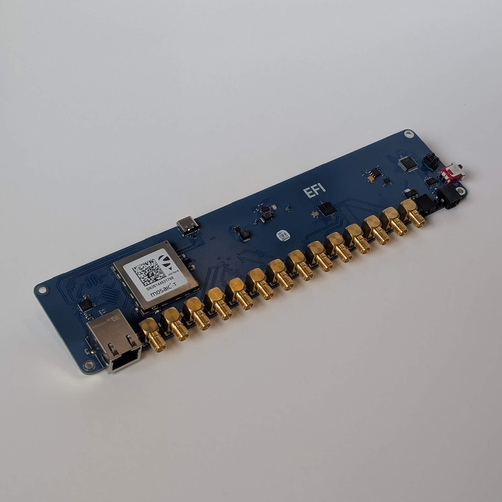
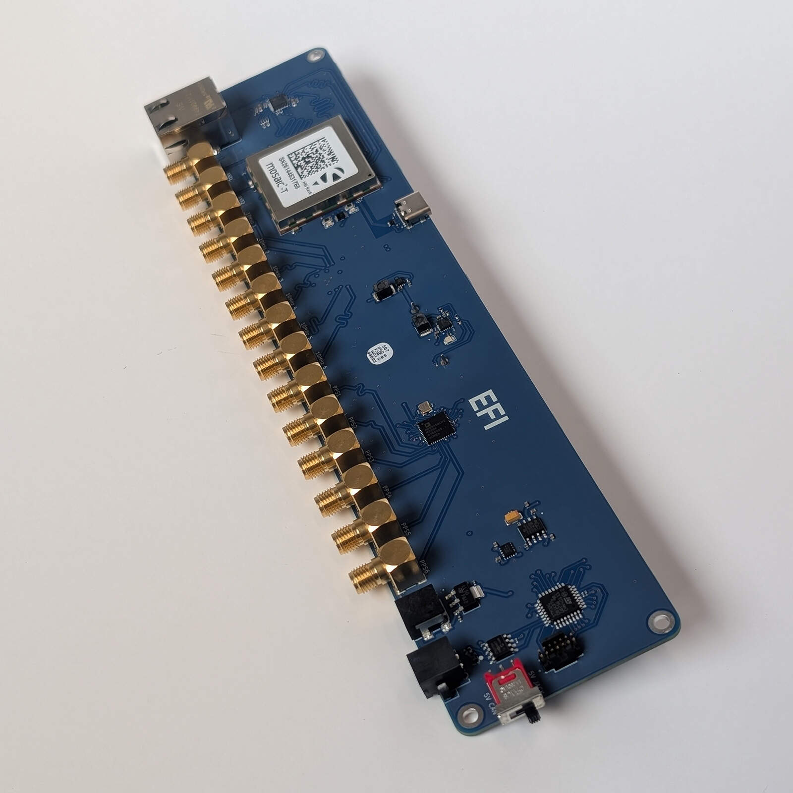
- 10 MHz6 × clock outputs
- 1 PPS5 × PPS outputs
- 1 hourVerified GNSS holdover
- 233 × 53 mmBoard size
Overview
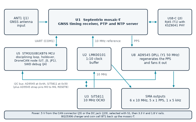
The PTPH1 turns a GNSS antenna signal into a holdover-capable time and frequency reference. A Septentrio mosaic-T receiver acquires GNSS, outputs a 1 PPS signal and reports the phase and frequency error of the 10 MHz clock that drives it. An on-board STM32G0B1KBT6 microcontroller reads that error over a serial link and steers a SiTime SiT5811 oven-controlled oscillator through its I²C frequency control word until the 10 MHz is locked to GNSS. An LMK00101 buffer distributes the 10 MHz to six SMA outputs and back to the receiver as its external frequency reference, which closes the loop through GNSS.
The receiver’s 1 PPS output drives an Analog Devices AD9545 DPLL, which regenerates it and fans it out to five 1 PPS outputs, aligned to the 10 MHz edge by a static skew trim. When GNSS is lost the microcontroller freezes the oscillator control word. The receiver keeps producing its PPS from the held 10 MHz for up to one hour, and the AD9545 keeps following it. The mosaic-T also serves IEEE 1588 PTP and NTP over the on-board Ethernet port. The microcontroller publishes the GNSS solution and the disciplining and holdover state to a flight controller as DroneCAN messages.
Key features
- Septentrio mosaic-T multi-band GNSS timing receiver (GPS, GLONASS, Galileo, BeiDou, QZSS, NavIC), antenna input on SMA with 3.3 V antenna supply
- Receiver-level interference mitigation (AIM+: narrow band, wide band and chirp jammers) and Galileo OSNMA support
- SiTime SiT5811 oven-controlled 10 MHz oscillator, ±1 ppb over temperature, steered to GNSS by the on-board microcontroller
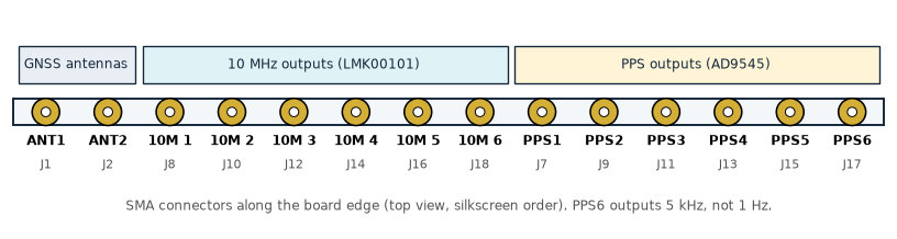
- Six 10 MHz outputs and five 1 PPS outputs on SMA connectors; the sixth PPS connector carries a 5 kHz signal
- 1 hour of GNSS-loss holdover, verified on hardware: the oscillator control word is frozen and the PPS keeps running
- PPS edges regenerated by an Analog Devices AD9545 DPLL and aligned to the 10 MHz edge by a static skew trim
- IEEE 1588 PTP and NTP server in the mosaic-T, on a 10/100 Mbit/s Ethernet port; mosaic-T web interface over Ethernet or USB-C
- DroneCAN (UAVCAN v0) node on classic CAN at 1 Mbit/s: GNSS Fix2 and Auxiliary messages, plus node status with the disciplining and holdover state
- STM32G0B1KBT6 Cortex-M0+ microcontroller with 128 KB flash and 144 KB SRAM; STDC14 debug and programming port
- Single 5 V supply from the CAN connector or from a 5 V power adapter on a DC jack, chosen with a slide switch; coin cell with charger keeps the receiver warm
- 233 × 53 mm board with four M2 mounting holes
Technical specifications
| Parameter | Value | Unit |
|---|---|---|
| Power input | ||
| CAN connector (J5 pin 2) supply voltage, typical / minimum / maximum | 5 / 4.5 / 5.5 | V |
| Input current from the CAN connector, typical / maximum | 760 / 820 | mA |
| Typical power consumption from the CAN connector | 3.8 | W |
| DC jack (J19) supply, 5 V power adapter | 5 | V |
| GNSS receiver | ||
| Receiver | Septentrio mosaic-T | |
| Interference mitigation (receiver) | AIM+: narrow band, wide band, chirp | |
| Constellations (single antenna, multi-frequency) | GPS, GLONASS, Galileo, BeiDou, QZSS, NavIC | |
| PPS output accuracy of the receiver (open sky) | 5 | ns |
| Time to first fix, cold start / warm start | < 45 / < 20 | s |
| Antenna supply voltage on ANT1 (VANT, fixed) | 3.3 | V |
| Antenna supply current limit (receiver) | 150 | mA |
| Antenna pre-amplification range (receiver) | 15 to 50 | dB |
| Time and frequency | ||
| Oscillator | SiTime SiT5811 OCXO | |
| Clock output frequency | 10 | MHz |
| Oscillator frequency stability over temperature | ±1 | ppb |
| Disciplining pull range as clamped on this board | ±3.125 | ppm |
| Oscillator frequency pull resolution | 0.05 | ppt |
| Oscillator holdover (manufacturer specification) | 1.5 over 8 hours | µs |
| GNSS-loss holdover verified on hardware | 1 | hour |
| 10 MHz outputs | 6 (10MHz 1 to 10MHz 6) | |
| 1 PPS outputs | 5 (PPS1 to PPS5) | |
| PPS6 output | 5 kHz | |
| PPS pulse width | 100 | ms |
| Output signal level of clock and PPS outputs | 1.8 V CMOS | |
| Interfaces | ||
| Ethernet | 10/100 Base-T, RJ45 | |
| USB | USB-C, USB 2.0 device (mosaic-T) | |
| CAN bus | 1 Mbit/s, classic CAN, 29-bit ID | |
| CAN protocol | DroneCAN (UAVCAN v0) | |
| CAN node ID | 42 (fixed in firmware) | |
| CAN bus termination | 120 Ω, selectable (JP1) | |
| Microcontroller | ||
| Device | STM32G0B1KBT6 (Cortex-M0+) | |
| Clock (internal HSI16 oscillator) | 16 | MHz |
| Flash / SRAM | 128 / 144 | KB |
| Mechanical and environmental | ||
| Board size | 233.0 × 53.0 × 1.6 | mm |
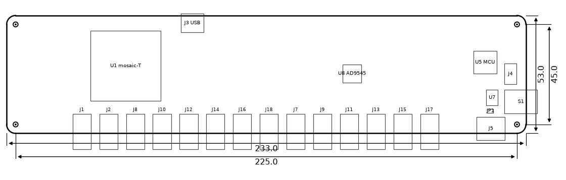
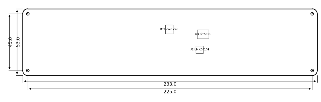
| Mounting holes | 4 × M2 (2.2 mm) on 225 × 45 mm | |
| Operating temperature (component rating) | -20 to +70 | °C |
The supply voltages and input currents are the figures given by the board's designer from bench measurements; the DC jack is intended for a 5 V power adapter. The receiver, oscillator and holdover figures are the manufacturers' published values (references [2] to [4]), not measurements of the PTPH1; the PPS accuracy of 5 ns is the receiver's xPPS accuracy with compensation of the sawtooth effect (below 1 ns needs the optional AtomiChron service, which is not part of this board). The AD9545 regenerates the PPS and the firmware aligns its edge to the 10 MHz edge with a static skew trim, which is calibrated for each unit; on the bench the edge-to-edge difference between the PPS and the 10 MHz output stayed within about 6 ns peak on one unit, which is an observation and not a guaranteed specification. The 1 hour holdover is the limit set by the firmware (the receiver is told to keep emitting its PPS for at most 3600 s after losing GNSS) and was verified on hardware by disconnecting the antenna for one hour. The oscillator's own holdover specification is longer than that. The pull range is set by the clamp value programmed in the oscillator; its maximum is ±400 ppm [4]. The clock and PPS drivers are supplied from the 1.8 V rail; their level into a 50 Ω load has not been measured. The operating temperature is the commercial-grade range of the oscillator and has not been tested on the board.
The board has no input fuse and no reverse-polarity protection on the 5 V input or the DC jack. Fit these externally if the supply is not protected.
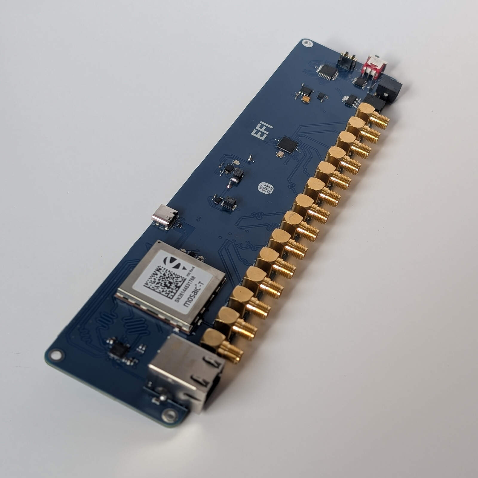
The board measures 233.0 × 53.0 mm and is 1.6 mm thick (six copper layers), with rounded corners. Four M2 mounting holes (2.2 mm pads) are spaced 225 × 45 mm, 4.0 mm in from each edge. The top side carries the mosaic-T, the microcontroller, the AD9545 and the connectors; the fourteen right-angle SMA connectors, the DC jack and the CAN connector run along the lower edge in the top view. The bottom side carries the SiT5811 oscillator, the LMK00101 buffer and the coin cell holder. All dimensions in the drawings are in millimetres. The heights of the components are not specified in this revision.
Absolute maximum ratings
Stresses beyond these values may cause permanent damage. They are estimated from the absolute maximum ratings of the components on each pin and have not been tested on the board. Absolute maximum ratings for the 5 V input (J5 pin 2) and the DC jack have not been determined: keep the supply within the limits in the specifications table.
| Parameter | Min | Max | Unit | Limited by |
|---|---|---|---|---|
| Voltage on CAN_H and CAN_L (DC) | -58 | +58 | V | MCP2562FD |
| Transient on CAN_H and CAN_L (ISO 7637) | -150 | +100 | V | MCP2562FD |
| ESD on CAN_H and CAN_L (HBM) | ±8 | kV | MCP2562FD | |
| Voltage on J4 signal pins (SWDIO, SWCLK, NRST) | -0.3 | 3.6 | V | STM32G0B1KBT6 (3.3 V I/O) |
Interfaces and connectors
The block diagram shows how the receiver, the oscillator, the clock buffer, the AD9545 and the microcontroller are connected. The 10 MHz path from the oscillator through the buffer to the SMA outputs and to the receiver does not depend on the firmware; the microcontroller steers the oscillator and configures the AD9545.
| Ref. | Function | Connector / mating part |
|---|---|---|
| J1 | ANT1: GNSS antenna input | SMA, right angle (Samtec SMA-J-P-GF-RA-SM1) |
| J2 | ANT2: not used by the mosaic-T | SMA, right angle |
| J8, J10, J12, J14, J16, J18 | 10 MHz outputs 10MHz 1 to 10MHz 6 | SMA, right angle |
| J7, J9, J11, J13, J15, J17 | PPS outputs PPS1 to PPS6 | SMA, right angle |
| J5 | Power (5 V) and CAN data bus | 2 × 3 pins, 2.54 mm pitch (Phoenix Contact 1844730). Mating part: Phoenix Contact 1027605 |
| JP1 | 120 Ω CAN termination | 2-pin jumper header (BC020-02-A-0200-0300-L-G) |
| S1 | 5 V source switch (5V CAN / 5V JACK) | Slide switch (500ASSP1M6QE) |
| J19 | DC power jack | Wurth Elektronik 694103107102 |
| J3 | USB-C (mosaic-T USB device port) | USB Type-C receptacle (Same Sky UJ20-C-H-G-SMT-1-P16-TR) |
| T1 | Ethernet | RJ45 with integrated magnetics (Wurth Elektronik 74990111217) |
| J4 | Debug and firmware programming (SWD) | 14-pin STDC14, 1.27 mm pitch (Samtec FTSH-107-01) |
| BT1 | Backup battery | Coin cell holder on the bottom side |
Power and CAN Data Bus (J5, S1)
J5 carries the 5 V supply and the CAN bus. The 5 V on pin 2 is an input: in the 5V CAN position the board draws its supply from it (about 0.76 A typical, see the specifications table), so the supply on the bus must be able to deliver that. The mating connector is the Phoenix Contact 1027605. Slide switch S1 chooses the supply: in the 5V CAN position the board runs from J5 pin 2, in the 5V JACK position it runs from the DC jack. The CAN transceiver and the termination are not affected by the switch.
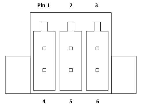
| Pin | Net | Type |
|---|---|---|
| 1 | NC | Not connected |
| 2 | 5V | Power input |
| 3 | GND | Power input |
| 4 | GND | Power input |
| 5 | CAN_H | I/O |
| 6 | CAN_L | I/O |
120 Ohm Termination Jumper (JP1)
Fitting a jumper on JP1 connects a 120 Ω termination resistor across the CAN bus. Fit it only on the two nodes at the ends of the bus.
STDC14 Debug Connector (J4)
J4 is designed for use with the ST-LINK-V3MINIE and can be used to debug the board or load firmware onto the microcontroller. The debugger must work at the 3.3 V logic level of the board (pin 3). The SWO and virtual COM port pins are not connected. Mating part: 14-pin STDC14 Cortex ribbon cable.
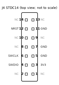
| Pin | Signal |
|---|---|
| 3 | 3.3 V (target voltage) |
| 4 | SWDIO |
| 6 | SWCLK |
| 12 | NRST |
| 5, 7, 11 | GND |
| 1, 2, 8, 9, 10, 13, 14 | Not connected |
USB-C (J3)
J3 is a USB Type-C connector wired to the USB device port of the mosaic-T, with ESD protection (USBLC6-2P6). It is a data connection only: the board is not powered from it. Connect it to a host computer to reach the mosaic-T web interface, which the receiver serves over USB at http://192.168.3.1 (the default address given by Septentrio for its USB Ethernet interface).
Ethernet (T1)
T1 is an RJ45 connector with integrated magnetics for a 10/100 Base-T network. A KSZ8041NLI Ethernet PHY connects it to the Ethernet (RMII) interface of the mosaic-T, which provides the web interface, the NTP server and the PTP engine. The PTPH1 firmware turns the receiver’s Ethernet interface on; the network address, NTP and PTP settings are those of the mosaic-T and are set through its web interface (references [2] and [3]).
Antenna Inputs (J1, J2)
ANT1 (J1) is the GNSS antenna input of the mosaic-T. The receiver supplies the antenna with 3.3 V on the same SMA connector (the supply pin of the module is tied to the 3.3 V rail), limited to about 150 mA, and switches the supply off on an overcurrent [3]. Use an active antenna rated for a 3.3 V supply, or one that does not need a supply with a DC block fitted. ANT2 (J2) is wired to the second antenna pad of the module footprint, which only the dual-antenna modules (mosaic-H) use [3]; the mosaic-T is a single-antenna module, so ANT2 is not used.
10 MHz Outputs
Six SMA connectors (10MHz 1 to 10MHz 6) carry the 10 MHz from the SiT5811 oscillator through the LMK00101 clock buffer. A seventh output of the buffer goes to the reference input of the mosaic-T. The frequency is steered to GNSS by the microcontroller, so the outputs are traceable to GNSS time while the receiver is locked, and keep the last frequency when GNSS is lost.
PPS Outputs
PPS1 to PPS5 are 1 Hz pulse-per-second outputs. They are generated by the AD9545 from the receiver’s PPS, so each pulse starts on the GPS second and is aligned to the 10 MHz outputs by the static skew trim. The pulse width is 100 ms. PPS6 (connector J17, OUT0CN of the AD9545) is not a PPS output: it carries a 5 kHz signal, which is the AD9545’s own zero-delay feedback tap and must not be used as a PPS reference.
DC Power Jack (J19)
The DC jack is an alternative to powering the board from J5. Move S1 to the 5V JACK position. It takes a 5 V power adapter and supplies the board in place of J5. The polarity and plug size are given in the Wurth Elektronik datasheet for 694103107102; the board’s designer notes a 4 mm plug.
Backup Battery (BT1)
A coin cell holder on the bottom side backs up the receiver’s supply (VDD_BAT) when the board loses power, so the mosaic-T keeps its almanac and settings and restarts warm (typically under 20 s) instead of cold (under 45 s) [2]. A BQ25306 charger charges the cell from the 5 V rail. Use only a rechargeable lithium coin cell of a type that suits the charger setting; do not fit a non-rechargeable cell.
Status LEDs
Two LEDs (D2 and D3) show the receiver’s status outputs (GPLED); see the mosaic-T hardware manual [3] for their meaning.
Jamming and Spoofing Resilience
The Septentrio mosaic-T has built-in interference monitoring and mitigation, which Septentrio calls AIM+. According to Septentrio, AIM+ monitors for interference and mitigates narrow band, wide band and chirp jammers, and the receiver is described as highly secure against jamming and spoofing [2]. The receiver also supports Galileo OSNMA (navigation message authentication) and RAIM+ (receiver autonomous integrity monitoring) [2]. Septentrio’s product datasheet gives no suppression figures, such as the jammer-to-signal ratio the receiver tolerates, so none are given here.
These functions run inside the mosaic-T. How well a PTPH1 performs near interference also depends on the antenna, where it is placed, and any external filtering or limiting, which are not part of this board.
When interference degrades the receiver’s clock data, the PTPH1 treats it like any other loss of GNSS: after 5 s of unhealthy data the oscillator control word is frozen, and the board keeps its 10 MHz and PPS outputs running for up to one hour. The state is reported in the DroneCAN node status. The holdover was verified by disconnecting the antenna, not by applying jamming or spoofing signals; the PTPH1 has not been tested against either. Whether OSNMA authentication is enabled on a unit has not been verified on this board, and the DroneCAN messages do not report interference or spoofing status.
Software and firmware
This board is a DroneCAN (UAVCAN v0) node. It uses classic CAN (CAN FD is not used) at 1 Mbit/s with 29-bit identifiers.
Node ID
Every node on a DroneCAN bus has a unique node ID from 1 to 127, which is the source address of the messages it sends. The PTPH1 has no node ID jumpers and no parameter service: its node ID is fixed in the firmware at 42. Give each node on the same bus its own ID and keep the flight controller’s own node ID different from 42.
Messages and Services
The board publishes three messages and answers one service. It does not subscribe to any message.
| Message / service | Type ID | Direction | Priority | Notes |
|---|---|---|---|---|
| uavcan.protocol.NodeStatus | 341 | Published, 1 Hz | 24 (low) | Health and mode; vendor status carries the disciplining and holdover state |
| uavcan.equipment.gnss.Fix2 | 1063 | Published, on each PVT (1 Hz) | 16 (medium) | GNSS position, velocity, time and fix status; at least once every 2 s |
| uavcan.equipment.gnss.Auxiliary | 1061 | Published, 1 Hz | 24 (low) | Satellite counts; dilution of precision unknown |
| uavcan.protocol.GetNodeInfo | 1 | Service | Priority of the request | Name "com.etherform.ptph", software version 0.1, hardware version 1.0, chip unique ID |
Node Status and Holdover State
The NodeStatus message reports the board’s health in its health field and the disciplining state of the 10 MHz in the vendor-specific status field. The mode field is INITIALIZATION while the board waits for the oscillator, the AD9545 and the receiver, or for a healthy GNSS clock (states 0 and 1 below), and OPERATIONAL afterwards.
NodeStatus health
| Health | Value | Meaning |
|---|---|---|
| OK | 0 | Locked to GNSS, or acquiring, and the AD9545 is following the PPS. |
| WARNING | 1 | Holdover is running and has not yet passed one hour, or the AD9545 is not following the PPS. |
| ERROR | 2 | Holdover has lasted more than one hour, or the oscillator is not answering on the I2C bus or its correction is at its limit (state 6). |
Disciplining states (vendor-specific status, bits 2 to 0)
| State | Name | Meaning |
|---|---|---|
| 0 | INIT | Waiting for the oscillator, the AD9545 and the receiver link. |
| 1 | WARMUP | Waiting for healthy GNSS clock data for 20 s. |
| 2 | ACQUIRE | Fast steering: pulling the frequency and phase of the oscillator in. |
| 3 | LOCKED | Slow tracking. The oscillator control word is saved for holdover. |
| 4 | HOLDOVER | GNSS lost for 5 s: the control word is frozen and the oscillator coasts. |
| 5 | REACQUIRE | GNSS back and healthy for 30 s: slew-limited return to lock. |
| 6 | FAULT | The oscillator is not answering, or the correction is at its limit. |
NodeStatus vendor-specific status field (16 bits)
| Bits | Meaning |
|---|---|
| 2 to 0 | Disciplining state |
| 7 to 3 | 0 |
| 8 | Holdover has lasted more than one hour |
| 9 | The AD9545 was also put into its own holdover (the receiver link was lost for more than 30 s during holdover) |
| 10 | The receiver reports a healthy GNSS clock |
| 15 to 11 | Elapsed holdover time in whole minutes (0 to 31, saturates at 31) |
Holdover works as follows. When the receiver’s clock data are unhealthy for 5 s (no fix, no external frequency, stale data, or no PPS), the microcontroller freezes the oscillator’s frequency control word. The receiver then keeps emitting its PPS from the held 10 MHz for up to 3600 s, and the AD9545 keeps following that PPS, so all outputs stay on frequency and time. Only if the serial link to the receiver itself is lost for more than 30 s does the microcontroller also put the AD9545 into its own holdover, so that it coasts on its tuning-word history. When GNSS returns and stays healthy for 30 s, the board steers back to lock; after a one-hour antenna disconnection on the bench the recovery needed only a fine correction.
GNSS Fix Message
The board publishes uavcan.equipment.gnss.Fix2 (type ID 1063) when the receiver sends a new position (once per second), and at least every 2 s otherwise. The table lists the fields as defined in the DroneCAN DSDL [7] and the value this board writes.
| Field | Type | Bits | Value written by the PTPH1 |
|---|---|---|---|
| timestamp | uavcan.Timestamp (uint56, us) | 56 | GNSS time in microseconds since the Unix epoch while the receiver has fine time, otherwise 0 |
| gnss_timestamp | uavcan.Timestamp (uint56, us) | 56 | GNSS time in microseconds since the Unix epoch (0 if unknown) |
| gnss_time_standard | uint3 | 3 | 2 (UTC) |
| num_leap_seconds | uint8 | 8 | 18 (fixed in the firmware) |
| longitude_deg_1e8, latitude_deg_1e8 | int37 | 37 each | Position in degrees times 1e8; 0 without a position |
| height_ellipsoid_mm, height_msl_mm | int27 | 27 each | Height in millimetres above the ellipsoid and above mean sea level; 0 without a position |
| ned_velocity | float32[3] | 96 | North, east and down velocity in m/s; 0 without a position |
| sats_used | uint6 | 6 | Number of satellites used in the position |
| status | uint2 | 2 | 0 NO_FIX, 1 TIME_ONLY (time valid or in holdover, no position), 3 FIX_3D |
| mode, sub_mode | uint4, uint6 | 4, 6 | 0, 0 (SINGLE) |
| covariance | float16[<=36] | 6 | Empty (length 0) |
| pdop | float16 | 16 | NaN (unknown) |
uavcan.equipment.gnss.Auxiliary (type ID 1061) carries the number of satellites in view and used; all dilution-of-precision fields are NaN.
Receiver Configuration
The firmware configures the mosaic-T at start-up and again if its data stop. It asks for the PVTGeodetic, ReceiverStatus and xPPSOffset blocks and NMEA GGA and GSV messages at 1 Hz on COM1 (115200 baud, 8N1, hardware flow control), turns the receiver’s Ethernet interface on, and sets the PPS output to 1 Hz, rising edge, no delay, GPS time scale, 100 ms wide, with a maximum synchronisation age of 3600 s. The receiver’s clock runs free on the 10 MHz reference: the microcontroller reads its clock bias and drift from the PVTGeodetic block and does not use the receiver’s own clock steering.
PX4 Configuration
PX4 can use the PTPH1 as a GNSS source through its uavcan driver. Set the following parameters (a reboot is needed after changing them). The parameter names are from the PX4 parameter reference [8]. Operation with a flight controller has not been tested.
| Parameter | Value | Notes |
|---|---|---|
| UAVCAN_ENABLE | 2 | Sensors automatic configuration. 0 = driver disabled, 1 = sensors with manual configuration, 3 also enables actuators |
| UAVCAN_SUB_GPS | 1 | Subscribe to uavcan.equipment.gnss.Fix2 |
| UAVCAN_BITRATE | 1000000 | Bus bit rate in bit/s; must match the 1 Mbit/s of the board |
| UAVCAN_NODE_ID | 1 to 125 | Node ID of the flight controller; it must not equal the PTPH1 node ID (42) |
Firmware
The PTPH1 ships pre-programmed with its firmware and is ready to use out of the box. The firmware is proprietary and its source code is not publicly released. Updated firmware images are supplied by Ether Form Inc.
Programming the Board
Connect an ST-LINK-V3MINIE to J4 (STDC14) to load firmware or debug over SWD. The board must be powered; the debugger takes its logic level from pin 3 (3.3 V). The microcontroller is an STM32G0B1KBT6, which STM32CubeProgrammer supports. Do not erase the whole device unless the replacement image is available.
Resources
- DroneCAN specification: CAN bus transport layer
- DroneCAN message definitions: DroneCAN DSDL (uavcan)
References
[1] “4.1 CAN bus transport layer – DroneCAN,” GitHub Pages, 2025. https://dronecan.github.io/Specification/4.1_CAN_bus_transport_layer/ (accessed Oct. 6, 2026).
[2] “mosaic-T: Compact multi-frequency GNSS timing receiver module,” Septentrio product datasheet, 2025.
[3] “mosaic-T Hardware Manual,” Septentrio, version 1.11.0.
[4] “SiT5811: 10 to 60 MHz, ±1 ppb Epoch Platform Precision OCXO,” SiTime datasheet, Rev. 0.12.
[5] “LMK00101 Ultra-low Jitter LVCMOS Fanout Buffer/Level Translator with Universal Input,” Texas Instruments datasheet SNAS572C.
[6] “AD9545: Quad Input, 10-Output, Dual DPLL/IEEE 1588 1 pps Synchronizer and Jitter Cleaner,” Analog Devices datasheet, Rev. C.
[7] “1063.Fix2.uavcan,” “1061.Auxiliary.uavcan” and “uavcan.protocol.NodeStatus,” DroneCAN DSDL. https://github.com/dronecan/DSDL (accessed Oct. 6, 2026).
[8] “Parameter Reference,” PX4 Autopilot User Guide. https://docs.px4.io/main/en/advanced_config/parameter_reference.html (accessed Oct. 6, 2026).
Request a quote or discuss your integration
Choose the inquiry type that fits. A standard bulk quote only needs a quantity and your contact details; engineering and customization inquiries need a short description of what you need.