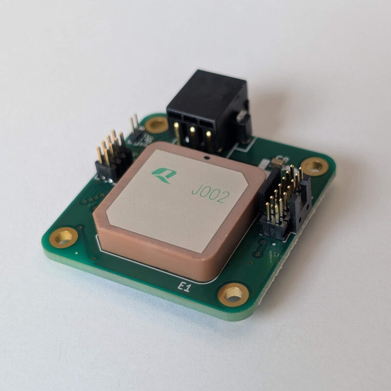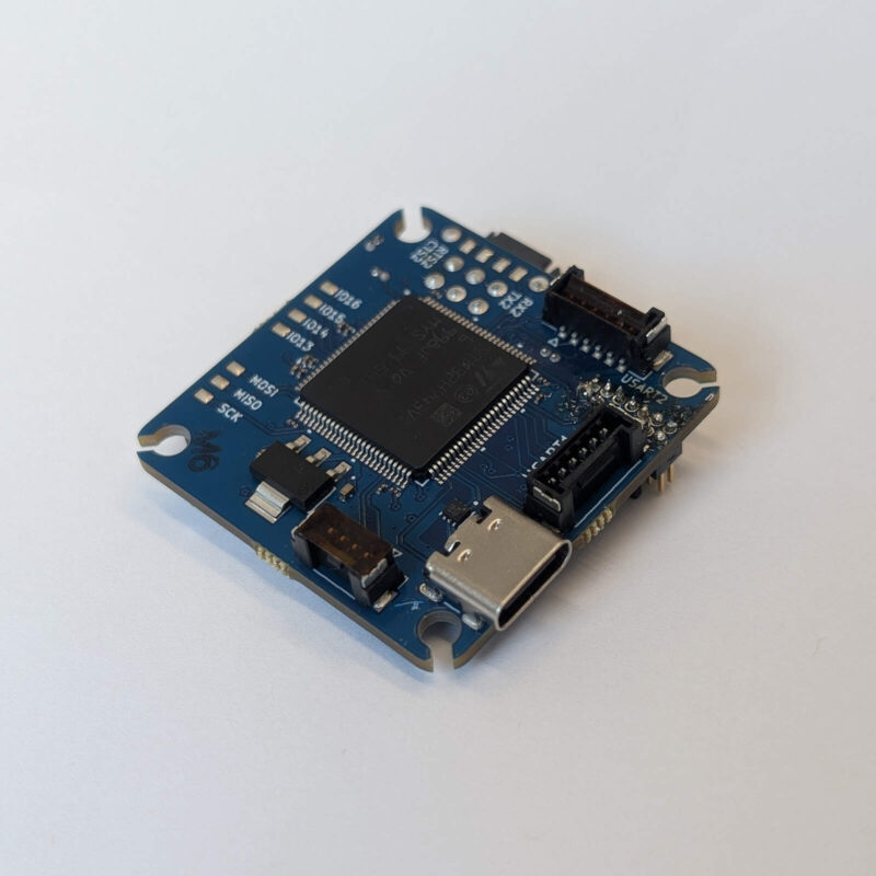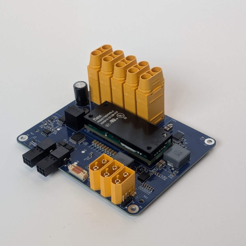
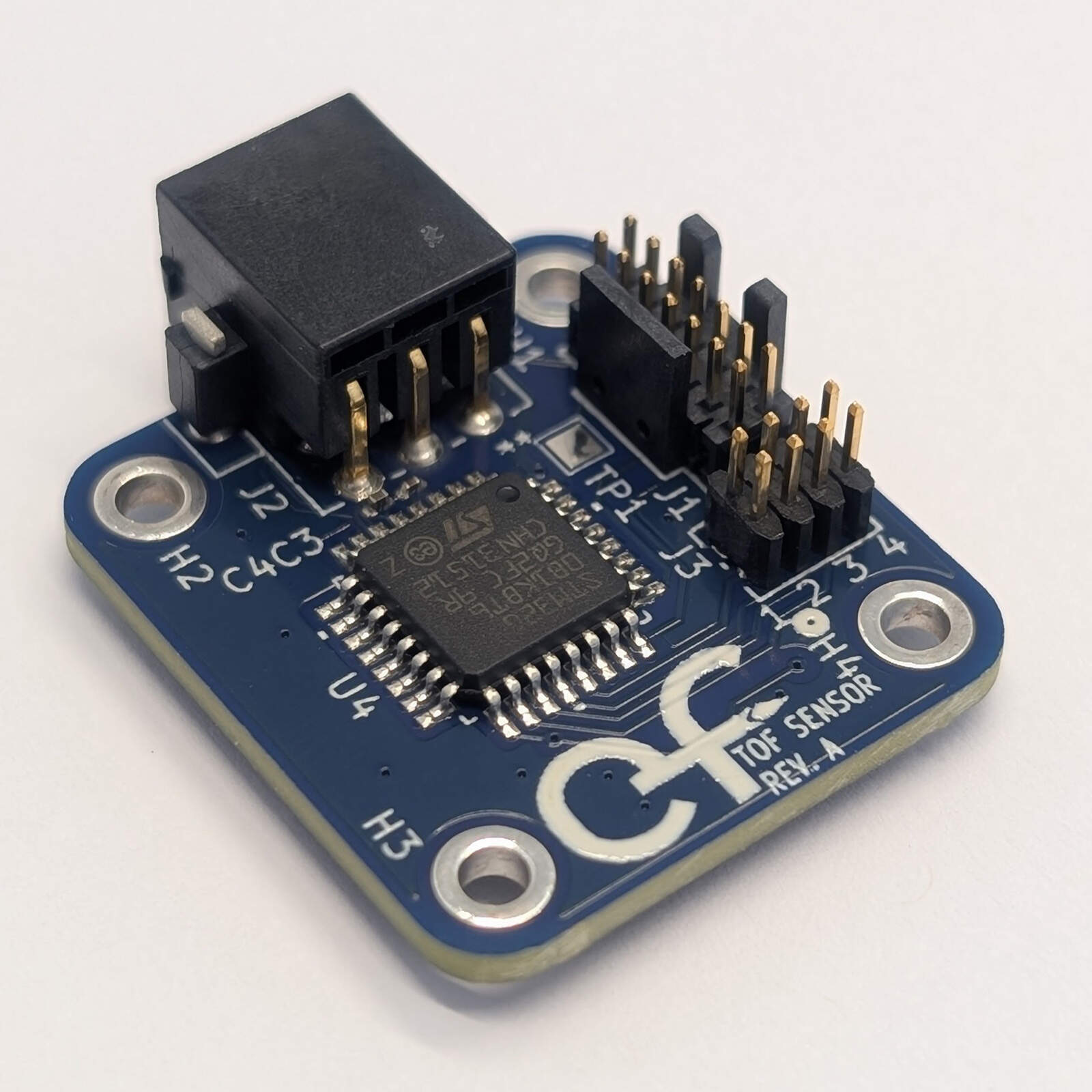
- 5 VNominal supply
- ≈ 4 mMaximum range (typical)
- 10 HzDefault update rate
- 26 × 26 mmBoard size
Overview
The TOF1 is a compact distance-sensing board for UAV flight-control systems. It measures distance with the STMicroelectronics VL53L1CB time-of-flight laser ranging sensor and sends the result to the flight controller over a DroneCAN bus. Running off of 5 V, an on-board STM32G0B1KBT6 microcontroller reads the sensor over I²C and publishes uavcan.equipment.range_sensor.Measurement messages at 10 measurements per second (10 Hz) by default, together with the standard DroneCAN node status. The TOF1 is out-of-the-box compatible with DroneCAN flight stacks including PX4, which uses it as a range finder.
Key features
- ST VL53L1CB time-of-flight laser ranging sensor, 27° field of view, up to about 4 m
- Short, long and automatic distance modes and a 25 to 250 ms measurement period, selectable over CAN
- DroneCAN over classic CAN at 1 Mbit/s (FDCAN peripheral, MCP2562FD transceiver), with selectable 120 Ω bus termination
- Publishes uavcan.equipment.range_sensor.Measurement, 10 Hz by default
- Node ID 32 to 47 selected with the J3 header jumpers, or any ID 1 to 127 stored over CAN
- STM32G0B1KBT6 Cortex-M0+ microcontroller with 128 KB flash and 144 KB SRAM
- Single 5 V supply (4.5 to 5.5 V)
- STDC14 debug and programming port for the ST-LINK-V3MINIE
- Compact 26 × 26 mm board
Technical specifications
| Parameter | Value | Unit |
|---|---|---|
| Electrical | ||
| Nominal supply voltage | 5 | V |
| Minimum operating voltage | 4.5 | V |
| Maximum operating voltage | 5.5 | V |
| Typical input current | 21.1 | mA |
| Maximum input current | 960 | mA |
| Typical power consumption | 105.5 | mW |
| Distance sensor | ||
| Sensor | ST VL53L1CB | |
| Maximum range (typical, white target in the dark) | up to ≈ 400 | cm |
| Minimum range | 4 | cm |
| Field of view (full angle, default 16 × 16 SPAD region) | 27 | degrees |
| Laser wavelength (Class 1) | 940 | nm |
| Measurement rate (default, programmable) | 10 (4 to 50) | Hz |
| Sensor I²C address (7-bit) | 0x29 | |
| CAN bus | ||
| Bit rate | 1 | Mbit/s |
| Frame format | Classic CAN, 29-bit ID | |
| Protocol | DroneCAN (UAVCAN v0) | |
| Node ID | 32 to 47 (J3) or 1 to 127 (stored) | |
| Bus termination | 120, selectable (JP1) | Ω |
| Microcontroller | ||
| Device | STM32G0B1KBT6 (Cortex-M0+) | |
| Clock (internal HSI16 oscillator) | 16 | MHz |
| Flash / SRAM | 128 / 144 | KB |
| Environmental | ||
| Operating temperature (component rating) | -20 to +85 | °C |
The range, field of view and laser figures are the typical values published by ST for the VL53L1CB (VL53L1 datasheet DS11786 Rev 16, reference [2]), not measurements of the TOF1. The range of up to about 4 m is for a white target (88 % reflectance) in the dark, full 27° field of view and no cover glass: ST gives 410 cm typical (330 cm minimum) in its lite mode and 320 cm typical in its ranging mode with a 16 ms timing budget. Dark or gray targets (17 % reflectance) reach less, typically 170 to 230 cm, and strong ambient light reduces the range sharply: ST gives 70 to 90 cm outdoors in overcast conditions. The operating temperature is the lowest common range of the board's components (the sensor is rated -20 to +85 °C) and has not been tested on the board. The board runs the microcontroller at 16 MHz from its internal oscillator.
The TOF1 has no reverse-polarity or over-voltage protection on its 5 V input and no ESD protection on the 5 V or CAN pins other than that of the MCP2562FD transceiver. The I²C bus between the microcontroller and the sensor has no external pull-up resistors; the internal pull-ups of the microcontroller (about 40 kΩ) are used.
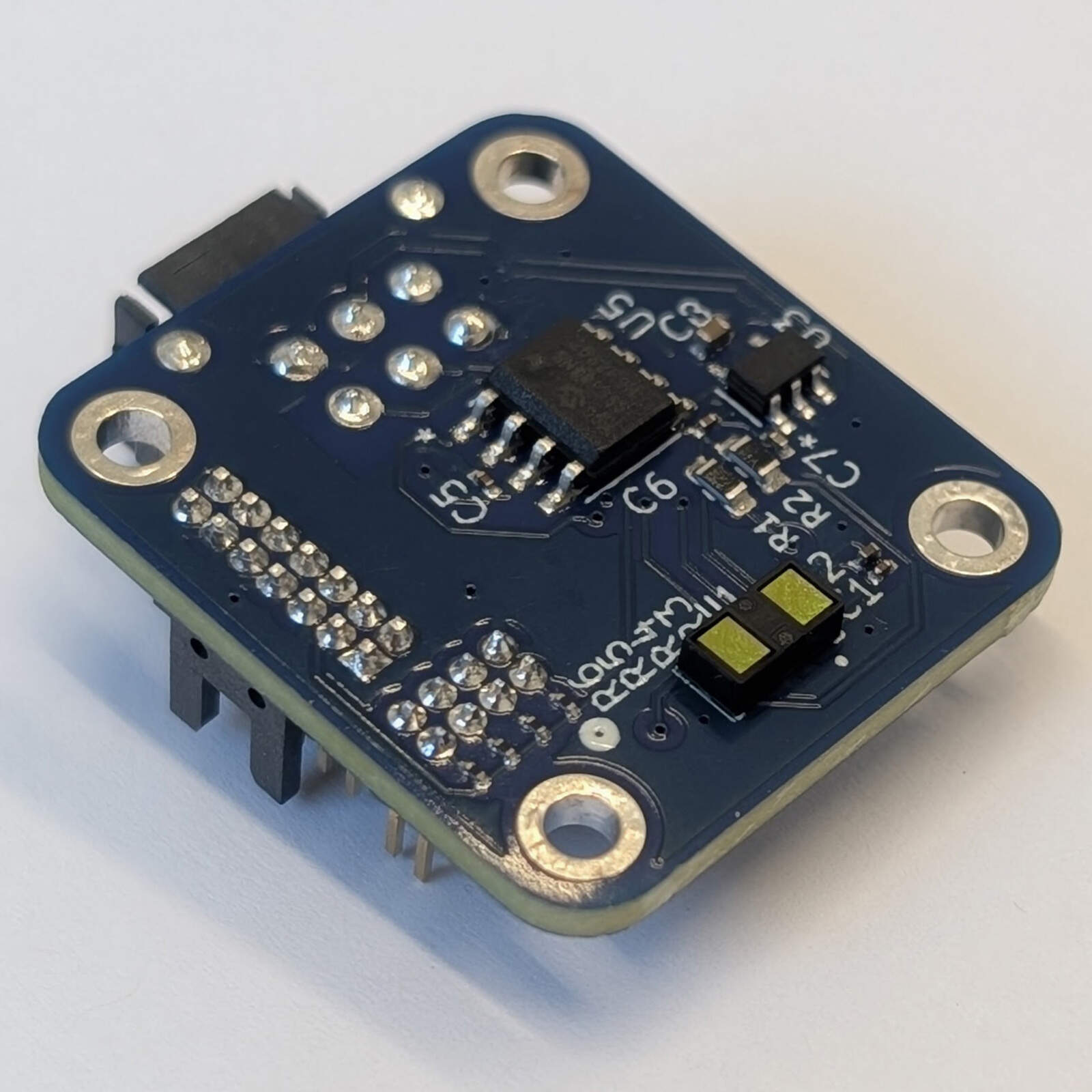
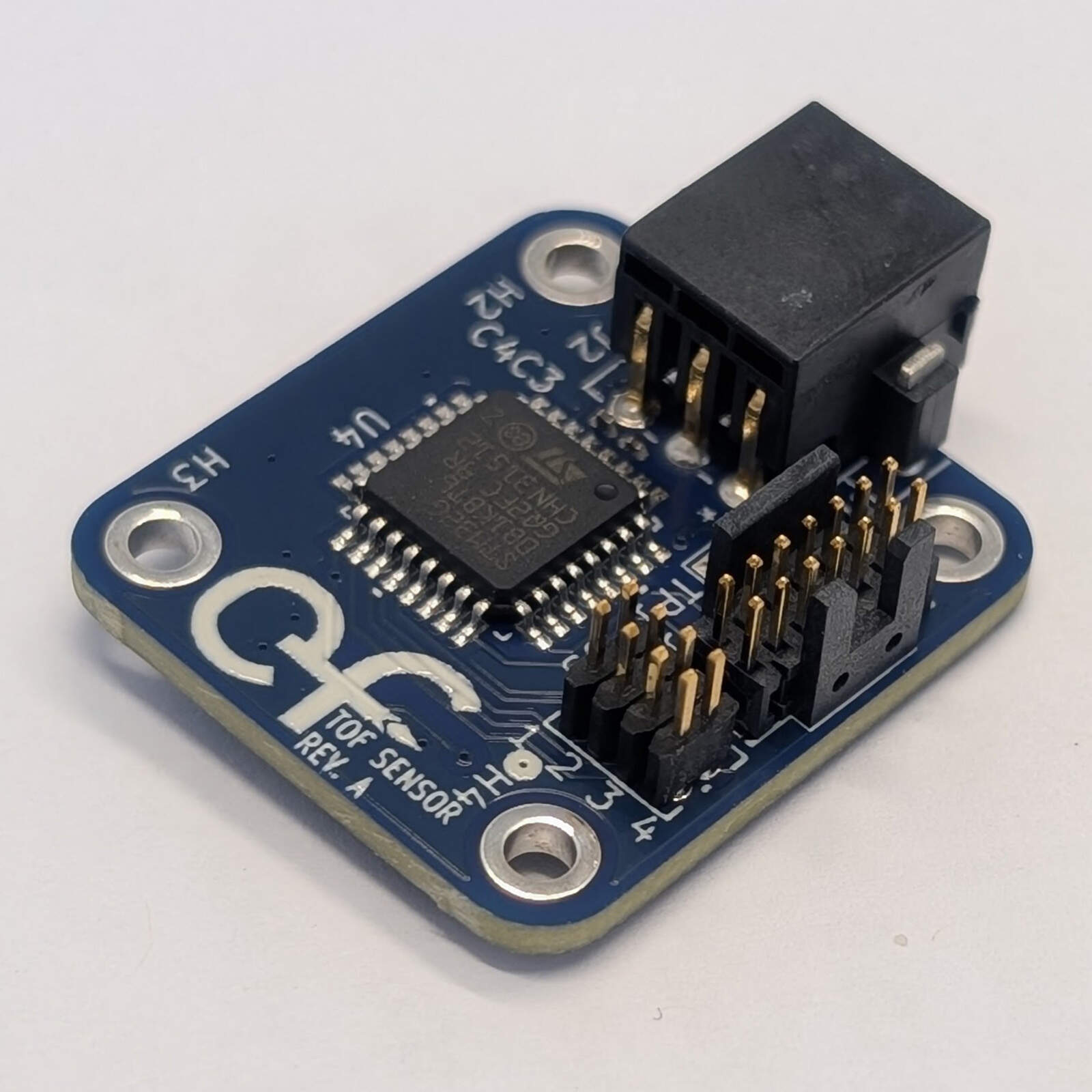
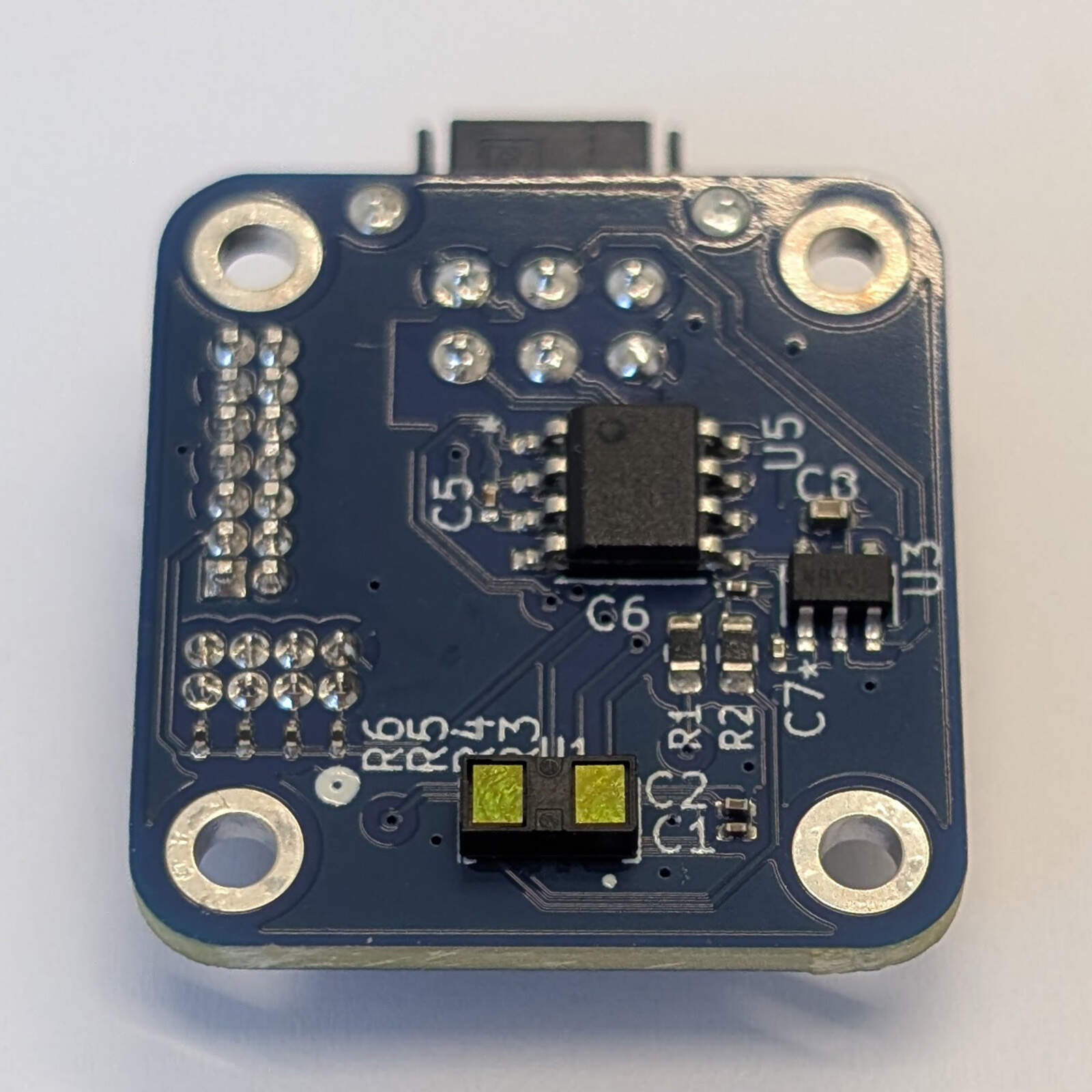
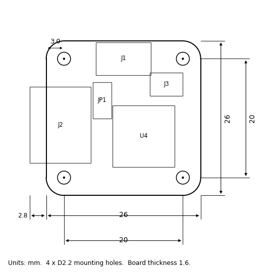
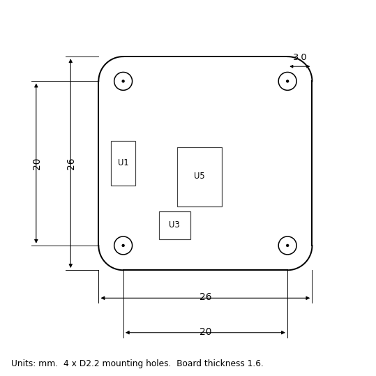
The board measures 26 × 26 mm and is 1.6 mm thick, with four M2 mounting holes (2.2 mm) on a 20 × 20 mm pattern, 3.0 mm in from each edge. The J2 connector overhangs the left edge by about 2.8 mm. The top view is the side with the microcontroller and the connectors; the VL53L1CB sensor, the CAN transceiver and the regulator are on the bottom side, so the sensor looks out of the bottom of the board and its field of view must be kept clear. All dimensions in the drawings are in millimetres.
Absolute maximum ratings
Stresses beyond these values may cause permanent damage. They are estimated from the absolute maximum ratings of the board’s components (the lowest limit among the parts connected to each pin) and have not been tested on the board. The 5 V input has no reverse-polarity or over-voltage protection.
| Parameter | Min | Max | Unit | Limited by |
|---|---|---|---|---|
| Supply voltage, 5V pin (J2 pin 2) | -0.3 | 6.5 | V | XC6222B281 input (MCP2562FD: 7.0 V) |
| Voltage on CAN_H and CAN_L (DC) | -58 | +58 | V | MCP2562FD |
| Transient on CAN_H and CAN_L (ISO 7637) | -150 | +100 | V | MCP2562FD |
| ESD on CAN_H and CAN_L (HBM) | ±8 | kV | MCP2562FD | |
| Voltage on J3 and J1 signal pins | -0.3 | 3.1 | V | STM32G0B1KBT6 (2.8 V I/O) |
| Storage temperature | -40 | +85 | °C | Board components |
Interfaces and connectors
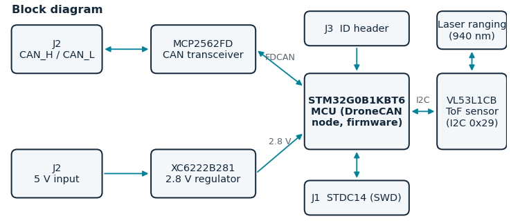
The block diagram shows how the connectors, the regulator, the CAN transceiver, the microcontroller and the sensor are connected.
| Ref. | Function | Connector / mating part |
|---|---|---|
| J2 | Power and CAN data bus | 2 × 3 pins, 2.54 mm pitch (Phoenix Contact 1844730). Mating part: Phoenix Contact 1027605 |
| JP1 | 120 Ω CAN termination | 1 mm pitch jumper (2 pins) |
| J1 | Debug and firmware programming | 14-pin STDC14 Cortex ribbon cable |
| J3 | Hardware ID (node ID) pins | 2 × 4 pins, 1.27 mm pitch (Amphenol 20021111-00008T4LF) |
Power and CAN Data Bus (J2)
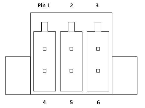
J2 carries the 5 V supply input and the CAN bus. The mating connector is the Phoenix Contact 1027605. The 5 V input is regulated to 2.8 V on the board, which powers the microcontroller, the sensor and the CAN transceiver logic supply.
| Pin | Net | Type |
|---|---|---|
| 1 | NC | Not connected |
| 2 | 5V | Power input |
| 3 | GND | Power input |
| 4 | GND | Power input |
| 5 | CAN_H | I/O |
| 6 | CAN_L | I/O |
120 Ω Termination Jumper (JP1)
Fitting a jumper on JP1 connects a 120 Ω termination resistor across the CAN bus. Fit it only on the two nodes at the ends of the bus. Jumper pitch: 1 mm.
STDC14 Debug Connector (J1)
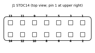
J1 is designed for use with the ST-LINK-V3MINIE and can be used to debug the board or load firmware onto the microcontroller. The debugger must work at the 2.8 V logic level of the board (pin 3). The SWO and virtual COM port pins are not connected. Mating part: 14-pin STDC14 Cortex ribbon cable.
| Pin | Signal |
|---|---|
| 3 | 2.8V (target voltage) |
| 4 | SWDIO |
| 5, 7, 11 | GND |
| 6 | SWCLK |
| 12 | NRST |
| 1, 2, 8, 9, 10, 13, 14 | Not connected |
Hardware ID Pins (J3)
J3 is an 8-pin header (1.27 mm pitch) with four rows. Each row has a signal pin (odd pin numbers 1, 3, 5, 7) beside a ground pin (even pin numbers 2, 4, 6, 8). Every signal pin has a 10 kΩ pull-up to 2.8 V, so an open row reads 0 and a jumper fitted across a row pulls its signal low, which sets that bit to 1. The four rows form a 4-bit value (0 to 15), with row 1 as the least significant bit, and the node ID is 32 plus this value. Each fitted jumper draws 0.28 mA (2.8 V through 10 kΩ). The board silkscreen numbers the rows 1 to 4.
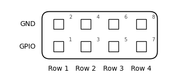
J3 pinout and function
| Row | Signal pin | GND pin | MCU pin | Signal | Bit (jumper fitted = 1) |
|---|---|---|---|---|---|
| 1 | 1 | 2 | PB5 | GPIO1 | Bit 0 (LSB), value 1 |
| 2 | 3 | 4 | PB4 | GPIO2 | Bit 1, value 2 |
| 3 | 5 | 6 | PB3 | GPIO3 | Bit 2, value 4 |
| 4 | 7 | 8 | PA15 | GPIO4 | Bit 3 (MSB), value 8 |
Example J3 settings (1 = jumper fitted) and the resulting node ID
| Row 1 | Row 2 | Row 3 | Row 4 | Value | Node ID |
|---|---|---|---|---|---|
| 0 | 0 | 0 | 0 | 0 | 32 |
| 1 | 0 | 0 | 0 | 1 | 33 |
| 0 | 1 | 0 | 0 | 2 | 34 |
| 0 | 0 | 1 | 0 | 4 | 36 |
| 0 | 0 | 0 | 1 | 8 | 40 |
| 1 | 1 | 1 | 1 | 15 | 47 |
Software and firmware
This board is a DroneCAN (UAVCAN v0) node. It uses classic CAN (CAN FD is not used) at 1 Mbit/s with 29-bit identifiers.
Node ID
Every node on a DroneCAN bus has a unique node ID from 1 to 127, which is the source address of the messages it sends. The TOF1 uses a static node ID that is chosen as follows. If a node ID has been stored in flash over CAN (see below), that ID is used as is. Otherwise the node ID is 32 plus the value set with the jumpers on J3, giving IDs 32 to 47; with no jumpers fitted the ID is 32. The jumpers are read at start-up only, so reset or power-cycle the board after changing one. Give each board on the same bus its own node ID, and keep it different from the flight controller’s own node ID. The sensor_id field of the range message is set to the node ID.
To store an ID over CAN, use the standard DroneCAN parameter services (for example in the DroneCAN GUI tool, or tools/can_param.py from the firmware repository): write the integer parameter NODE_ID (1 to 127) with uavcan.protocol.param.GetSet. The stored ID overrides the J3 jumpers and is used after the node restarts, which can be requested with uavcan.protocol.RestartNode. Writing 0 removes the stored ID so that the J3 jumpers are used again. The ID can also be stored while programming with tools/flash_and_check.py --set-node-id. Writing flash stops the processor for a few tens of milliseconds, so do not change the ID while the sensor is in use.
Range Measurement Message
The board publishes uavcan.equipment.range_sensor.Measurement (type ID 1050) at the measurement rate, 10 Hz by default. The table lists the fields exactly as defined in the DroneCAN DSDL [4]; the last column shows the value this board writes.
uavcan.equipment.range_sensor.Measurement (DTID 1050)
| Field | Type | Bits | Value written by the TOF1 |
|---|---|---|---|
| timestamp | uavcan.Timestamp (uint56, microseconds) | 56 | 0 (unknown) |
| sensor_id | uint8 | 8 | The node ID |
| beam_orientation_in_body_frame | uavcan.CoarseOrientation (int5[3] roll, pitch, yaw, and bool orientation_defined) | 16 | Defined (orientation_defined = 1): pointing down by default, roll 0, pitch -90°, yaw 0; set with BEAM_ORIENT |
| field_of_view | float16 | 16 | Field of view in radians: 0.471 (27°) |
| sensor_type | uint5 | 5 | 2 (SENSOR_TYPE_LIDAR) |
| reading_type | uint3 | 3 | See the next table |
| range | float16 | 16 | Distance in metres |
reading_type values
| reading_type | Value | Meaning |
|---|---|---|
| READING_TYPE_UNDEFINED | 0 | Range is unknown |
| READING_TYPE_VALID_RANGE | 1 | The range field contains a valid distance |
| READING_TYPE_TOO_CLOSE | 2 | The range field contains the minimum range of the sensor |
| READING_TYPE_TOO_FAR | 3 | The range field contains the maximum range of the sensor |
The reading type is derived from the range status that the VL53L1CB reports with each measurement. The type is a 3-bit field; the total size of the message payload is 120 bits (15 bytes).
Programmable Parameters
Four integer parameters can be read and written over CAN with uavcan.protocol.param.GetSet (for example from the DroneCAN GUI tool or tools/can_param.py). They are stored in flash and kept across restarts: the node ID in the flash page at 0x0801F000 (page 62), the distance mode in the page at 0x0801E800 (page 61) and the measurement period in the page at 0x0801F800 (page 63). An erased page means the default.
| Parameter | Range | Default | Meaning |
|---|---|---|---|
| NODE_ID | 0 to 127 | 0 | Node ID stored in flash; 0 uses the J3 jumpers. Applied after a restart |
| DIST_MODE | 1 to 3, or 0 | 0 (long) | VL53L1CB distance mode: 1 = short, 2 = long, 3 = automatic (long, switching to short for near targets), 0 = default (long). Applied at once |
| MEAS_PERIOD_MS | 25 to 250, or 0 | 0 (100 ms) | Measurement period in ms, 0 selects the default of 100 ms (10 Hz). Applied at once |
| BEAM_ORIENT | 1 to 10, or 0 | 0 (down) | Direction of the beam reported in every range message: 1 = down, 2 = up, 3 = forward, 4 to 10 = horizontal, turned right by 45, 90, 135, 180, 225, 270 or 315°. Applied at once |
The beam orientation is sent in the beam_orientation_in_body_frame field as a DroneCAN coarse orientation: roll, pitch and yaw in multiples of 15° (90° is 6). The default, a beam pointing down, is pitch -90°. PX4 turns this into the distance sensor rotation (downward, upward, or horizontal in 45° steps of yaw); other angles it treats as a custom rotation.
The sensor timing budget is derived from the measurement period: it is the largest of 20, 33, 50, 100 and 200 ms that is no more than 80% of the period, so the default period of 100 ms uses a 50 ms budget. The headroom is needed: with the budget equal to the period the sensor gave a failed reading between valid ones. A longer budget gives a longer range and better repeatability, but needs a longer period, so the maximum range in the specifications table is reached only with the long distance mode and a slow measurement rate (a 200 ms budget needs a period of 250 ms).
In automatic mode (DIST_MODE 3) the firmware chooses the distance mode. It starts in long mode and changes to short mode after three readings in a row that are a valid distance below 900 mm, below the sensor’s minimum range, or unusable; it returns to long mode after three readings in a row that are out of range or unusable, or a valid distance above 1200 mm. The thresholds are 300 mm apart, changes are at least one second apart, and the first reading after a change is not sent. The mode in use is reported in the sub-mode field of NodeStatus (1 = short, 2 = long). The choice is kept in RAM, so a restart begins in long mode.
Messages and Services
| Message / service | Type ID | Direction | Notes |
|---|---|---|---|
| uavcan.equipment.range_sensor.Measurement | 1050 | Published, 10 Hz default | Distance; period programmable |
| uavcan.protocol.NodeStatus | 341 | Published, 1 Hz | |
| uavcan.protocol.GetNodeInfo | 1 | Service | Name "CAN ToF Sensor", software version 1.0, hardware version 1.0, chip unique ID |
| uavcan.protocol.param.GetSet | 11 | Service | NODE_ID, DIST_MODE, MEAS_PERIOD_MS, BEAM_ORIENT |
| uavcan.protocol.param.ExecuteOpcode | 10 | Service | Save (values are stored when set) and erase (clears all four stored settings) |
| uavcan.protocol.RestartNode | 5 | Service | Applies a new node ID |
Fault Reporting
The board reports the state of the sensor in the health field of NodeStatus. If the VL53L1CB does not answer on the I²C bus, the health is ERROR; if the sensor answers but delivers no measurement for 3 seconds, the health is WARNING. The vendor-specific status code tells the two apart.
| Health | Vendor status code | Meaning |
|---|---|---|
| OK | 0 | The sensor is ranging. |
| WARNING | 2 | No measurement has been received from the sensor for 3 seconds. |
| ERROR | 1 | The VL53L1CB never answered on the I²C bus; no range is published. |
PX4 Configuration
PX4 uses the TOF1 as a range finder through its uavcan driver. Set the following parameters (a reboot is needed after changing them). The parameter names and defaults are from the PX4 parameter reference [3].
| Parameter | Value | Notes |
|---|---|---|
| UAVCAN_ENABLE | 2 | Sensors automatic configuration (3 also enables actuators). 0 = driver disabled, 1 = sensors with manual configuration |
| UAVCAN_SUB_RNG | 1 | Subscribe to uavcan.equipment.range_sensor.Measurement (default 0, disabled) |
| UAVCAN_RNG_MIN | 0.0 | Minimum valid range in metres (default 0.0) |
| UAVCAN_RNG_MAX | 4.0 | Maximum valid range in metres (default 999.0); use about 1.3 for short mode |
| UAVCAN_BITRATE | 1000000 | Bus bit rate in bit/s (default 1000000); must match the 1 Mbit/s of the board |
| UAVCAN_NODE_ID | 1 to 125 | Node ID of the flight controller (default 1); it must not equal the TOF1 node ID (32 to 47 with the J3 jumpers) |
Firmware
The TOF1 ships pre-programmed with its firmware and is ready to use out of the box. This section is only needed by developers and by anyone who wants to update the firmware.
The firmware (libcanard based, MIT licence) is published in the TOF1 repository of the Ether Form Inc GitHub organization:
github.com/Ether-Form-Inc/TOF1
Programming the Board
Connect an ST-LINK-V3MINIE to J1 (STDC14) to load firmware or debug over SWD. The repository’s tools/flash_and_check.py programs the board and then checks over CAN that the node answers GetNodeInfo. The node ID, distance mode, measurement period and beam orientation stored in flash can be set and cleared with the tools below.
Configuration and Test Tools
The firmware repository includes Python scripts for use with a serial USB-CAN adapter (a ‘USB-CAN analyzer’ at 2 Mbaud, set to 1 Mbit/s CAN). Any DroneCAN GUI tool can also read and set the parameters.
| Script | Purpose |
|---|---|
| can_monitor.py | Listen to the bus and show the node status and range messages, including the beam orientation |
| can_range_live.py | Print every range reading, the distance mode in use and the beam orientation, continuously |
| can_getnodeinfo.py | Read GetNodeInfo (name, version, health) from a node |
| can_param.py | List, read and set the parameters (NODE_ID, DIST_MODE, MEAS_PERIOD_MS, BEAM_ORIENT) |
| flash_and_check.py | Program and check a board; store the node ID with --set-node-id |
For example, can_param.py 32 set BEAM_ORIENT up changes the beam orientation reported by node 32 (the words down, up, forward, right, back and left, or a number from 1 to 10, are accepted), and can_param.py 32 set DIST_MODE auto selects automatic distance mode. Changes to DIST_MODE, MEAS_PERIOD_MS and BEAM_ORIENT take effect at once and are kept in flash; a new NODE_ID is used after the node restarts. The orientation in use is also carried in every range message, and can_range_live.py shows it.
Resources
- Firmware source code (TOF1 repository): github.com/Ether-Form-Inc/TOF1
- DroneCAN specification: CAN bus transport layer
- DroneCAN message definitions: DroneCAN DSDL (uavcan)
References
[1] “4.1 CAN bus transport layer – DroneCAN,” GitHub Pages, 2025. https://dronecan.github.io/Specification/4.1_CAN_bus_transport_layer/ (accessed Sept. 9, 2026).
[2] “VL53L1: Time-of-Flight long-distance ranging sensor with advanced multizone and multiobject detection,” STMicroelectronics datasheet DS11786 Rev 16, January 2026. https://www.st.com/resource/en/datasheet/vl53l1.pdf (accessed Oct. 5, 2026).
[3] “Parameter Reference,” PX4 Autopilot User Guide. https://docs.px4.io/main/en/advanced_config/parameter_reference.html (accessed Oct. 5, 2026).
[4] “1050.Measurement.uavcan,” DroneCAN DSDL, uavcan/equipment/range_sensor. https://github.com/dronecan/DSDL (accessed Oct. 5, 2026).
Request a quote or discuss your integration
Choose the inquiry type that fits. A standard bulk quote only needs a quantity and your contact details; engineering and customization inquiries need a short description of what you need.