- 36–72 VBattery input
- 12 / 7.2 / 5 VRegulated outputs
- 2 × CANDroneCAN buses
- 107 × 84 mmBoard size
Overview
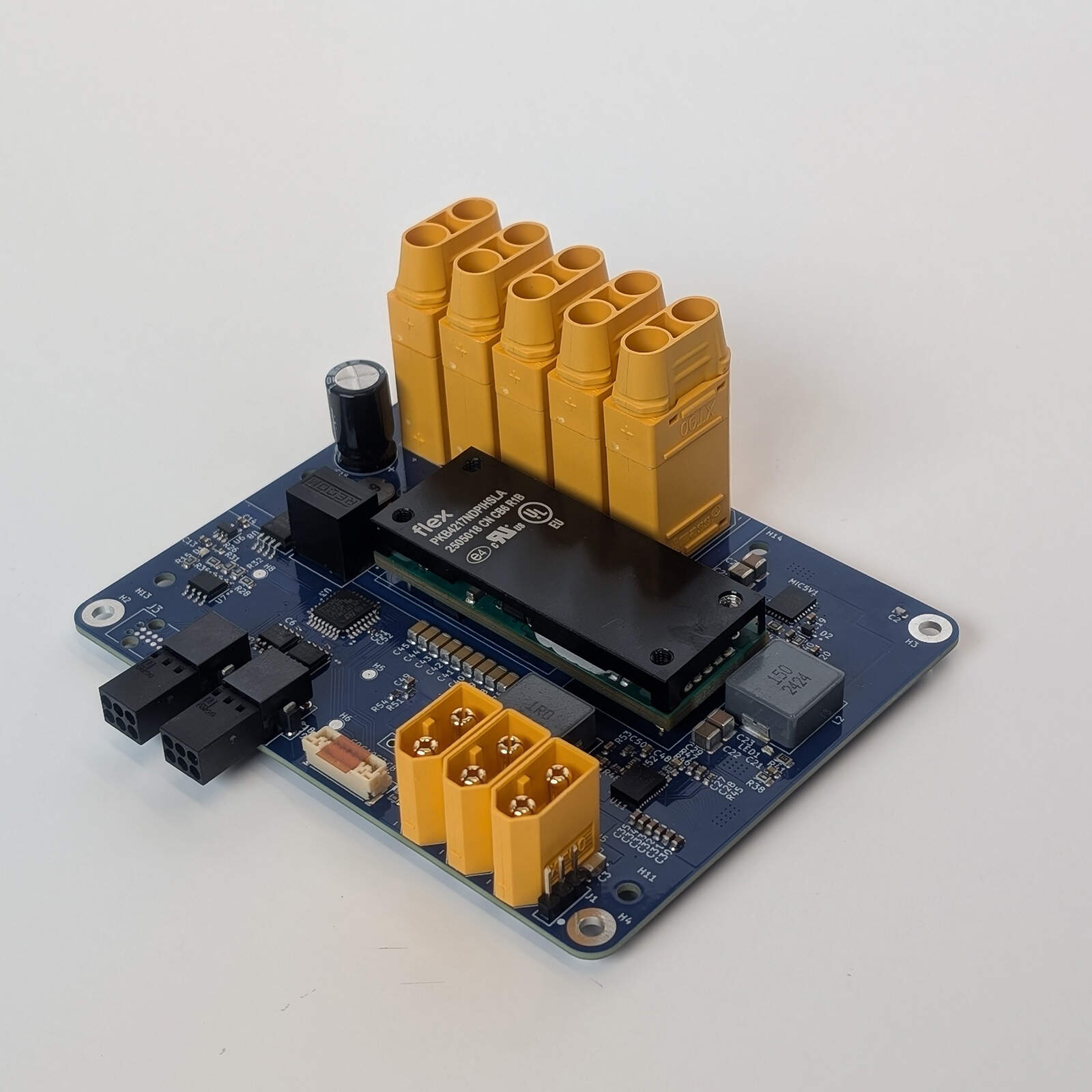
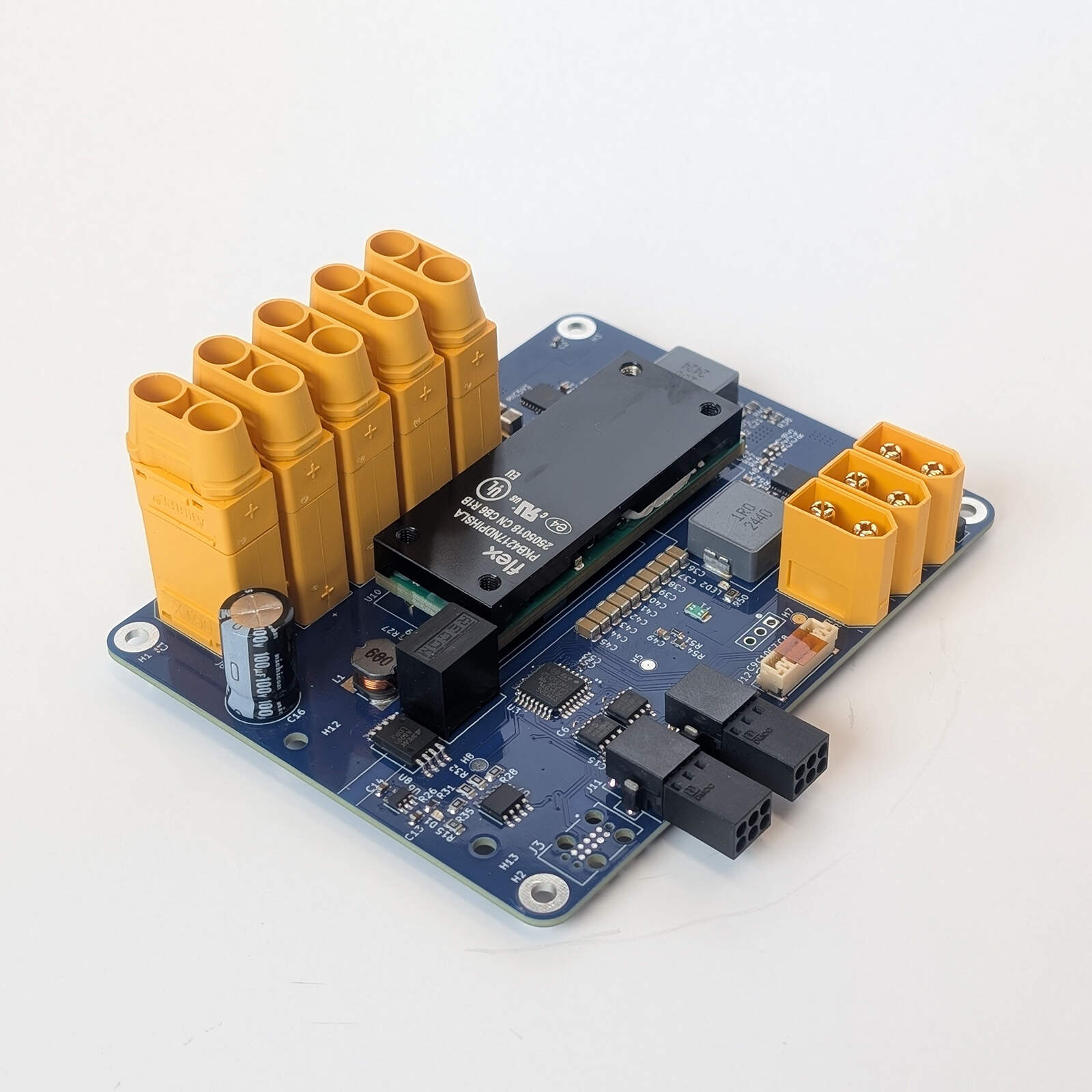
The PDB1 is a power distribution board for UAS. The battery comes in on XT90 connectors and is passed to the motor controllers. An isolated converter turns it into a 12 V main rail, and 5 V and 7.2 V rails are derived from that, with their own connectors for payload, companion computer and servo power. An on-board STM32G0B1KBT6 microcontroller measures the battery voltage, the main rail current, four external thermistors and its own temperature, and reports them as DroneCAN messages on two CAN buses together with the standard node status. The board only measures: it does not switch or limit any rail. The PDB1 answers the standard DroneCAN configuration services, so it can be set up with any DroneCAN tool.
Key features
- Battery input of 36 to 72 V on five XT90 connectors, passed straight through to motor controllers
- Isolated 12 V main rail (Flex PKB4213DPI, up to 22 A), with 5 V and 7.2 V rails derived from it
- Measures the battery voltage across an isolation barrier, the 12 V rail current (with a latching overcurrent fault) and four thermistor temperatures
- Two DroneCAN buses over classic CAN at 1 Mbit/s (MCP2562FD transceivers), one primary and one backup
- Publishes CircuitStatus, Temperature and, for PX4, BatteryInfo (voltage, 12 V rail current, estimated charge), 10 Hz by default
- Node ID 64 by default, or any ID 1 to 127 stored over CAN
- STM32G0B1KBT6 Cortex-M0+ microcontroller with 128 KB flash and 144 KB SRAM
- Tag-Connect TC2050 programming and debug port
- 107 × 84 mm board
Technical specifications
| Parameter | Value | Unit |
|---|---|---|
| Power input | ||
| Battery input voltage, operating | 36 to 72 | V |
| Main converter turn-on / turn-off input voltage (typical) | 35 / 33 | V |
| Main converter | Flex PKB4213DPI | |
| Isolation, battery to rails (converter test voltage) | 2250 | Vdc |
| Power outputs | ||
| 12 V rail output voltage (J7, J11 and J14 pin 1) | 12.0 (11.6 to 12.4) | V |
| 12 V rail maximum output current (converter rating) | 22 | A |
| 5 V rail output voltage (J5, J11 and J14 pin 2) | 5.0 | V |
| 5 V rail maximum output current (regulator rating) | 9 | A |
| 7.2 V rail output voltage (J4) | ≈ 7.2 | V |
| 7.2 V rail maximum output current (regulator rating) | 15 | A |
| 7.2 V rail fuse (F1) | 20 | A |
| Measurements | ||
| Battery voltage range (full scale) | 0 to 70 | V |
| Battery voltage resolution (12 bit) | 17 | mV |
| 12 V rail current range (ACS711KEXLT-31AB) | ±31 | A |
| 12 V rail current resolution (12 bit) | 18 | mA |
| Overcurrent fault (latching) at | ≈ ±31 | A |
| Thermistor inputs | 4 × 10 kΩ NTC (B = 3435 K) | |
| Telemetry rate (default, programmable) | 10 (4 to 50) | Hz |
| CAN bus | ||
| Buses | 2 (FDCAN1 primary, FDCAN2 backup) | |
| Bit rate | 1 | Mbit/s |
| Frame format | Classic CAN, 29-bit ID | |
| Protocol | DroneCAN (UAVCAN v0) | |
| Node ID | 64 (default) or 1 to 127 (stored) | |
| Bus termination | None on the board | |
| Microcontroller | ||
| Device | STM32G0B1KBT6 (Cortex-M0+) | |
| Clock (internal HSI16 oscillator) | 16 | MHz |
| Flash / SRAM | 128 / 144 | KB |
| Mechanical and environmental | ||
| Board size | 107.2 × 84.5 × 1.6 | mm |
| Operating temperature (component rating) | -40 to +85 | °C |
The converter figures are the values published by the manufacturers (references [2] to [5]), not measurements of the PDB1: the output currents are the converter ratings and the board has not been load tested. The main converter figures are those of the Flex PKB4213D (12 V, 22 A / 264 W) in the PKB4000D series [2]. The main converter accepts 36 to 75 V, but the 5 V supply of the battery-side amplifier (U5, Recom R-78HE5.0-0.3) accepts at most 72 V and the battery voltage measurement reads up to about 70 V, so 72 V is the limit for the board. The 5 V and 7.2 V output voltages are set by feedback resistors (0.8 V and 0.6 V references). The battery voltage resolution and the current resolution are one step of the 12-bit converter; the readings are averaged between messages. The accuracy of the measurements has not been specified. The battery voltage reading agreed with a bench supply at 50.7 V. The operating temperature is the lowest common range of the board's components (set by the microcontroller); the main converter must be derated at high temperature [2]. It has not been tested on the board.
The PDB1 has no input fuse, reverse-polarity protection or surge clamp on the battery input: the only fuse (F1) protects the 7.2 V output. Fit these externally. The ACS711 overcurrent fault latches until the board is power cycled.
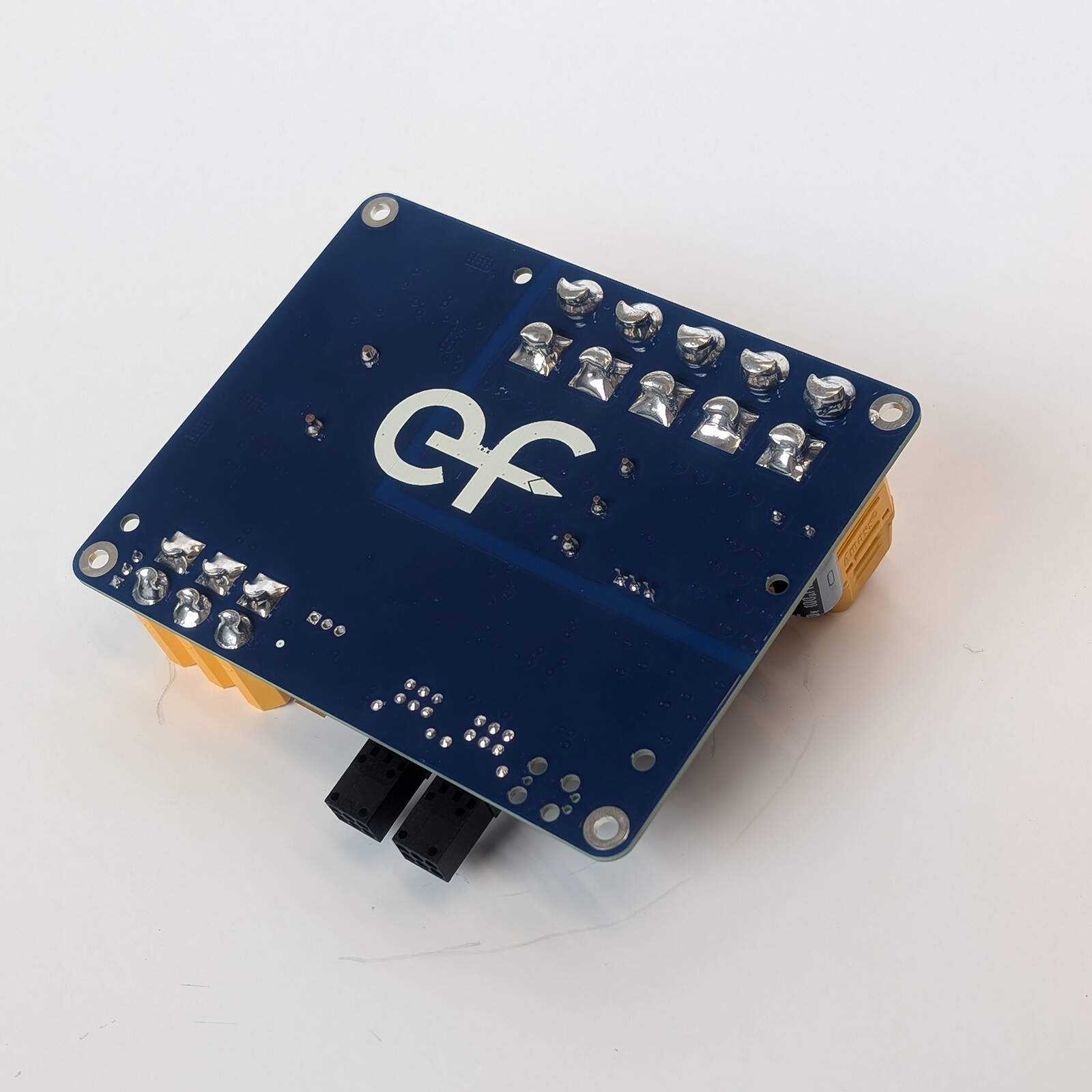
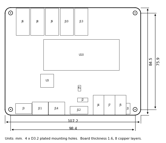
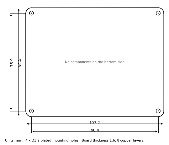
The board measures 107.2 × 84.5 mm and is 1.6 mm thick (eight copper layers), with rounded corners of about 4.4 mm radius. Four plated M3 mounting holes (3.2 mm, with 6.4 mm pads) are spaced 98.4 × 75.9 mm, about 4.4 mm in from each edge. The five XT90 battery connectors run along the top edge in the top view; the CAN, thermistor and programming connectors are along the bottom edge and the XT60 output connectors in the bottom right corner. All components are on the top side. The bottom side has no components, only the pins of the through-hole connectors and a logo. All dimensions in the drawings are in millimetres. The heights of the components are not specified in this revision.
Absolute maximum ratings
Stresses beyond these values may cause permanent damage. They are estimated from the absolute maximum ratings of the board’s components (the lowest limit among the parts connected to each pin) and have not been tested on the board. The battery input has no reverse-polarity or over-voltage protection.
| Parameter | Min | Max | Unit | Limited by |
|---|---|---|---|---|
| Battery input voltage, continuous | -0.5 | +80 | V | Main converter (U10). Keep to 72 V in operation: R-78HE5.0-0.3 (U5) |
| Battery input transient (ETSI EN 300 132-2) | 100 | V | Main converter (U10) | |
| Voltage on CAN_H and CAN_L (DC) | -58 | +58 | V | MCP2562FD |
| Transient on CAN_H and CAN_L (ISO 7637) | -150 | +100 | V | MCP2562FD |
| ESD on CAN_H and CAN_L (HBM) | ±8 | kV | MCP2562FD | |
| Voltage on J3 signal pins | -0.3 | 3.6 | V | STM32G0B1KBT6 (3.3 V I/O) |
| Storage temperature | -40 | +85 | °C | Board components |
Interfaces and connectors
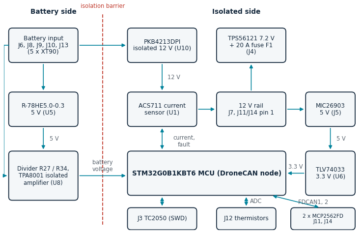
The block diagram shows how the connectors, the converters, the measurement circuits, the CAN transceivers and the microcontroller are connected. The battery side (battery negative, called PGND on the schematic) is galvanically isolated from the rest of the board (signal ground, SGND) by the main converter and by the isolated amplifier that measures the battery voltage.
| Ref. | Function | Connector / mating part |
|---|---|---|
| J6, J8, J9, J10, J13 | Battery input and battery distribution (five in parallel) | Amass XT90 (male, on the board) |
| J4 | 7.2 V output (servo power) | Amass XT60 (male) |
| J5 | 5 V output (microcontroller power) | Amass XT60 (male) |
| J7 | 12 V output (camera power) | Amass XT60 (male) |
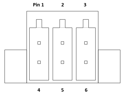
| J11 | CAN bus 1 (primary), with 12 V and 5 V | 2 × 3 pins, 2.54 mm pitch (Phoenix Contact 1844730). Mating part: Phoenix Contact 1027605 |
| J14 | CAN bus 2 (backup), with 12 V and 5 V | 2 × 3 pins, 2.54 mm pitch (Phoenix Contact 1844730). Mating part: Phoenix Contact 1027605 |
| J12 | Thermistor inputs | 8-pin JST GH, 1.25 mm pitch (BM08B-GHS-TBT). Mating housing: JST GHR-08V-S |
| J3 | Programming and debug (SWD) | Tag-Connect TC2050-IDC footprint (no connector fitted) |
| J1, J2 | Test headers (not fitted) | 3 pins (Amphenol G800W305018EU) |
Battery Input and Distribution (J6, J8, J9, J10, J13)
The five XT90 connectors are wired in parallel on the battery bus. One is the battery input and the others pass the battery voltage directly to motor controllers; the schematic names J13 ‘Power Connector’ and J6, J8, J9 and J10 ‘Motor Power Control’. The battery voltage is not fused or switched on its way to these connectors. The main converter takes its power from the same bus, and a 68 µH inductor with capacitors filters the input of the 5 V regulator (U5) that supplies the isolated amplifier. All five connectors have the same pinout; the positive pin is marked on the connector.
| Pin | Net | Type |
|---|---|---|
| 1 | Battery + | Power |
| 2 | Battery – (PGND) | Power |
Power Outputs (J4, J5, J7)
Three XT60 connectors carry the regulated rails, each with the positive pin marked on the connector and the other pin on signal ground. J7 is the 12 V main rail (the schematic calls it the camera connector), J5 the 5 V rail and J4 the 7.2 V rail, which is fed through the 20 A fuse F1. The 7.2 V converter has no enable switch under firmware control: it starts by itself as soon as the 12 V rail is present, with a soft start. Two green LEDs show that the 5 V rail (LED1) and the 7.2 V rail (LED2) are present.
| Connector | Pin 1 | Pin 2 |
|---|---|---|
| J7 | 12 V | GND |
| J5 | 5 V | GND |
| J4 | 7.2 V (after fuse F1) | GND |
CAN Data Buses (J11, J14)
J11 is CAN bus 1 (FDCAN1, the primary bus) and J14 is CAN bus 2 (FDCAN2, the backup bus). Each connector carries the CAN signals and also the 12 V and 5 V rails as outputs, so that a node on the bus can be powered from them. They are outputs of the board: do not connect a supply to them. The mating connector is the Phoenix Contact 1027605. The board has no termination resistors on either bus; fit a 120 Ω termination at both ends of the bus, for example in the harness.
| Pin | Net | Type |
|---|---|---|
| 1 | 12 V | Power output |
| 2 | 5 V | Power output |
| 3 | GND | Ground |
| 4 | GND | Ground |
| 5 | CAN_H | I/O |
| 6 | CAN_L | I/O |
Thermistor Inputs (J12)
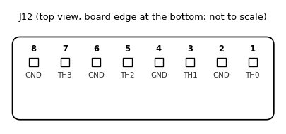
J12 is an 8-pin JST GH connector (1.25 mm pitch) with four thermistor inputs. Each input has a signal pin (odd pin numbers 1, 3, 5, 7) beside a ground pin (even pin numbers 2, 4, 6, 8). Connect a 10 kΩ NTC thermistor between the signal pin and the ground pin; the BOM specifies the Semitec 103JT-100 (B = 3435 K). The thermistors are not on the board. Each input has a 200 kΩ pull-up to the 5 V rail and a 100 pF filter capacitor. An input with no thermistor reads open: the firmware detects this, reports no temperature for that input and raises no warning. A shorted input is reported as a warning. An input can also be ignored with TEMP_DISABLE.
| Pin | Net | MCU pin | DroneCAN device ID |
|---|---|---|---|
| 1 | TH0 | PA5 | 0 |
| 3 | TH1 | PA4 | 1 |
| 5 | TH2 | PA3 | 2 |
| 7 | TH3 | PA2 | 3 |
| 2, 4, 6, 8 | GND |
Programming Port (J3)
J3 is a Tag-Connect TC2050-IDC footprint: ten pads that a TC2050-IDC cable presses against, with no connector fitted (the schematic names it the ST-LINK V3 MINIE connector). It carries SWD for programming and debugging; the debugger must work at the 3.3 V logic level of the board (pin 1). The pads on pins 6, 7 and 8 are not connected.

| Pin | Signal |
|---|---|
| 1 | 3.3 V (target voltage) |
| 2 | SWDIO |
| 3, 5, 9 | GND |
| 4 | SWCLK |
| 10 | NRST |
| 6, 7, 8 | Not connected |
Test Headers (J1, J2)
J1 and J2 are 3-pin footprints that are not fitted. J2 has ground (pin 1), the microcontroller reset NRST (pin 2) and 3.3 V (pin 3). Pin 2 of J1 is the enable of the 7.2 V converter, which the firmware never drives.
Software and firmware
This board is a DroneCAN (UAVCAN v0) node. It uses classic CAN (CAN FD is not used) at 1 Mbit/s with 29-bit identifiers, on two buses at the same time with the same node ID.
Node ID
Every node on a DroneCAN bus has a unique node ID from 1 to 127, which is the source address of the messages it sends. The PDB1 has no node ID jumpers. It uses a static node ID of 64 unless another one has been stored in flash over CAN. Give each board on the same bus its own node ID, and keep it different from the flight controller’s own node ID.
To store an ID over CAN, use the standard DroneCAN parameter services (for example in the DroneCAN GUI tool, or tools/can_param.py from the firmware repository): write the integer parameter NODE_ID (1 to 127) with uavcan.protocol.param.GetSet. The stored ID is used after the node restarts, which can be requested with uavcan.protocol.RestartNode. Writing 0 removes the stored ID, which gives 64 again. The ID can also be stored while programming with tools/flash_and_check.py --set-node-id. Writing flash stops the processor for a few tens of milliseconds.
Telemetry Messages
The board publishes three messages on the primary bus (CAN bus 1, J11): uavcan.equipment.power.CircuitStatus (type ID 1091) twice per period, once for the battery and once for the 12 V rail, uavcan.equipment.device.Temperature (type ID 1110) once for each temperature, and uavcan.equipment.power.BatteryInfo (type ID 1092) once per period when a battery has been configured. The period is 100 ms (10 Hz) by default. The tables list the fields exactly as defined in the DroneCAN DSDL [7]; the last column shows the value this board writes. CircuitStatus and Temperature fit in one CAN frame; BatteryInfo is sent as a transfer of four frames.
uavcan.equipment.power.CircuitStatus (DTID 1091)
| Field | Type | Bits | Value written by the PDB1 |
|---|---|---|---|
| circuit_id | uint16 | 16 | 0 = battery input, 1 = 12 V rail |
| voltage | float16 | 16 | Circuit 0: the battery voltage in volts. Circuit 1: NaN (not measured). |
| current | float16 | 16 | Circuit 0: NaN (not measured). Circuit 1: the rail current in amps, positive out of the main converter. |
| error_flags | uint8 | 8 | Circuit 1: OVERCURRENT (4) while the overcurrent fault is asserted. Otherwise 0. |
uavcan.equipment.device.Temperature (DTID 1110)
| Field | Type | Bits | Value written by the PDB1 |
|---|---|---|---|
| device_id | uint16 | 16 | 0 to 3 = thermistors TH0 to TH3 (J12 pins 1, 3, 5, 7); 4 = the microcontroller die |
| temperature | float16 | 16 | Temperature in kelvin. An input with no thermistor fitted (reads open), a shorted input, or a disabled input is not sent. |
| error_flags | uint8 | 8 | 0 |
uavcan.equipment.power.BatteryInfo (DTID 1092)
| Field | Type | Bits | Value written by the PDB1 |
|---|---|---|---|
| temperature | float16 | 16 | NaN (not known) |
| voltage | float16 | 16 | The measured battery voltage in volts |
| current | float16 | 16 | The 12 V rail current in amps. The motor current is drawn through each motor controller and is not measured. |
| average_power_10sec | float16 | 16 | NaN (not known) |
| remaining_capacity_wh, full_charge_capacity_wh, hours_to_full_charge | float16 | 16 each | 0 |
| status_flags | uint11 | 11 | STATUS_FLAG_IN_USE (1) |
| state_of_health_pct | uint7 | 7 | 127 (unknown) |
| state_of_charge_pct | uint7 | 7 | Estimated from the battery voltage |
| state_of_charge_pct_stdev | uint7 | 7 | 20 |
| battery_id, model_instance_id | uint8, uint32 | 8, 32 | 0 |
| model_name | uint8[<32] | 5 + 8 per byte | PDB |
The messages carry no timestamp. The values are averages of the readings taken since the previous message: about a dozen readings per input in a 100 ms period.
How the readings are measured
| Reading | Input | Conversion |
|---|---|---|
| Battery voltage | PA0 | Resistor divider (68 kΩ over 300 Ω), TPA8001 isolated amplifier (gain 8.2) and a differential amplifier (gain 1.3) in front of the ADC: 0.0468 V at the ADC per battery volt, so the ADC is at full scale at about 70.5 V. |
| 12 V rail current | PA1 | ACS711KEXLT-31AB: 45 mV/A at 3.3 V, zero current at half the supply. Its output follows the same 3.3 V as the ADC reference, so the reading does not depend on the supply. |
| Thermistors TH0 to TH3 | PA5, PA4, PA3, PA2 | 10 kΩ NTC (B = 3435 K) with a 200 kΩ pull-up to 5 V. The result is corrected for the measured 3.3 V reference. |
| Microcontroller temperature | Internal sensor | Factory calibration at 30 and 130 °C, corrected for the measured reference. |
| Overcurrent fault | PA8 | The ACS711 FAULT output, low when the current exceeds about 31 A in either direction. It stays low until the power is cycled. |
Programmable Parameters
Six integer parameters can be read and written over CAN with uavcan.protocol.param.GetSet (for example from the DroneCAN GUI tool or tools/can_param.py). They are stored in flash and kept across restarts: the node ID in the flash page at 0x0801F000 (page 62), the telemetry period in the page at 0x0801F800 (page 63), the thermistor mask in the page at 0x0801E800 (page 61), the number of battery cells at 0x0801E000 (page 60), the full cell voltage at 0x0801D800 (page 59) and the empty cell voltage at 0x0801D000 (page 58). An erased page means the default.
| Parameter | Range | Default | Meaning |
|---|---|---|---|
| NODE_ID | 0 to 127 | 0 | Node ID stored in flash; 0 uses 64. Applied after a restart. |
| PUB_PERIOD_MS | 0, or 20 to 250 | 0 | Milliseconds between telemetry messages; 0 uses 100 (10 Hz). Applied at once. |
| TEMP_DISABLE | 0 to 15 | 0 | Bit mask of thermistors to ignore (bit 0 = TH0 ... bit 3 = TH3). An ignored thermistor is never reported and never raises a warning, even if fitted. 0 = none ignored. Inputs with no thermistor are detected automatically. Applied at once. |
| BATT_CELLS | 0 to 20 | 0 | Number of cells in the battery. 0 = not set: BatteryInfo is not published. Applied at once. |
| BATT_CELL_FULL | 0 to 255 | 0 | Voltage of a full cell: 2.50 V + n × 10 mV; 0 uses 4.20 V (170). Applied at once. |
| BATT_CELL_EMPTY | 0 to 255 | 0 | Voltage of an empty cell, same units; 0 uses 3.30 V (80). Applied at once. |
Messages and Services
| Message / service | Type ID | Direction | Notes |
|---|---|---|---|
| uavcan.equipment.power.CircuitStatus | 1091 | Published, 10 Hz default | Bus 1 only. Battery voltage; 12 V rail current |
| uavcan.equipment.device.Temperature | 1110 | Published, 10 Hz default | Bus 1 only. Thermistors and microcontroller |
| uavcan.equipment.power.BatteryInfo | 1092 | Published, 10 Hz default | Bus 1 only, when BATT_CELLS is set. For PX4 |
| uavcan.protocol.NodeStatus | 341 | Published, 1 Hz | Both buses |
| uavcan.protocol.GetNodeInfo | 1 | Service | Name "PDB", software version and git commit, hardware version 3 (Rev C), chip unique ID |
| uavcan.protocol.param.GetSet | 11 | Service | NODE_ID, PUB_PERIOD_MS, TEMP_DISABLE, BATT_CELLS, BATT_CELL_FULL, BATT_CELL_EMPTY |
| uavcan.protocol.param.ExecuteOpcode | 10 | Service | Save (values are stored when set) and erase (clears all six stored settings) |
| uavcan.protocol.RestartNode | 5 | Service | Applies a new node ID |
PX4 Battery and Arming
PX4 does not read CircuitStatus. It builds its DroneCAN battery from uavcan.equipment.power.BatteryInfo when its UAVCAN_SUB_BAT parameter is enabled [8], and its pre-arm check refuses to arm when the battery data is missing, more than 5 seconds old, or shows a low or critical charge. The PDB1 publishes BatteryInfo once the number of cells is set with BATT_CELLS (for example can_param.py 64 set BATT_CELLS 12). It is not published before that, because the charge it carries is estimated from the battery voltage and would only be a guess; PX4 then reports a missing battery.
The estimate is linear between the empty and full voltage of a cell (BATT_CELL_EMPTY, BATT_CELL_FULL; 3.30 V and 4.20 V by default) multiplied by the number of cells. A real battery’s voltage is not linear in its charge and sags under load, so the percentage is approximate. The current in BatteryInfo is the 12 V rail current only: the motor current is drawn from the battery through each motor controller and is not measured by the PDB1, so PX4’s current and consumed-charge figures count only the 12 V rail until a battery current sensor is added. This has not yet been tested with a flight controller.
Primary and Backup Bus
The board runs one node with one node ID on both buses. CAN bus 1 (J11, FDCAN1) is the primary bus: it carries the telemetry and NodeStatus, and answers the services. CAN bus 2 (J14, FDCAN2) is the backup bus: it carries NodeStatus, so the node is visible on that bus, and answers the services, but it carries no telemetry. A request is answered on the bus it arrived on, and a parameter written on one bus applies to the board. Each bus recovers by itself from bus-off, 100 ms after the controller goes off the bus.
Fault Reporting
The board reports its state in the health field of NodeStatus, and the vendor-specific status code is a bit mask that says why. An overcurrent trip or a failed thermistor is reported as a warning; if the ADC stops delivering samples, no telemetry is valid and the health is ERROR.
| Health | Vendor status code (bit mask) | Meaning |
|---|---|---|
| OK | 0 | Nothing to report. |
| WARNING | 1 | Overcurrent: the ACS711 fault output is asserted. It stays asserted until the board is power cycled. |
| WARNING | 2 | An enabled thermistor input is shorted. An input that reads open has no thermistor fitted and is not a fault. |
| ERROR | 4 | The ADC is not delivering samples. |
The bits are added when several apply, for example 3 for an overcurrent trip and a failed thermistor.
Firmware
The PDB1 ships pre-programmed with its firmware and is ready to use out of the box. This section is only needed by developers and by anyone who wants to update the firmware.
The firmware (libcanard based, MIT licence) is published in the Ether Form Inc GitHub organization, where all of the Ether Form firmware lives:
Programming the Board
Connect an ST-LINK with a Tag-Connect TC2050-IDC cable to J3 to load firmware or debug over SWD. The board must be powered: the debugger takes its target voltage from J3 pin 1, so the battery input has to be connected. The repository’s tools/flash_and_check.py programs the board and then checks over CAN that the node answers GetNodeInfo. The node ID, telemetry period and thermistor mask stored in flash can be set and cleared with the tools below.
Configuration and Test Tools
The firmware repository includes Python scripts for use with a serial USB-CAN adapter (a ‘USB-CAN analyzer’ at 2 Mbaud, set to 1 Mbit/s CAN). Any DroneCAN GUI tool can also read and set the parameters.
| Script | Purpose |
|---|---|
| can_telemetry.py | Show the battery voltage, 12 V rail current, estimated charge, temperatures and node status live |
| can_getnodeinfo.py | Read GetNodeInfo (name, version, health) from a node |
| can_param.py | List, read and set the parameters (NODE_ID, PUB_PERIOD_MS, TEMP_DISABLE, BATT_CELLS, BATT_CELL_FULL, BATT_CELL_EMPTY) |
| flash_and_check.py | Program and check a board; store the node ID with --set-node-id |
For example, can_param.py 64 set TEMP_DISABLE 1 makes the board ignore the thermistor on TH0 even if one is fitted. Changes to PUB_PERIOD_MS and TEMP_DISABLE take effect at once and are kept in flash; a new NODE_ID is used after the node restarts.
Resources
- Firmware source code (Ether Form Inc GitHub organization): github.com/Ether-Form-Inc
- DroneCAN specification: CAN bus transport layer
- DroneCAN message definitions: DroneCAN DSDL (uavcan)
References
[1] “4.1 CAN bus transport layer – DroneCAN,” GitHub Pages, 2025. https://dronecan.github.io/Specification/4.1_CAN_bus_transport_layer/ (accessed Sept. 9, 2026).
[2] “PKB4000D series, Fully regulated DC-DC converters, Input 36-75 V, Output up to 25 A / 300 W,” Flex Power Modules technical specification 28701-BMR674 01 Rev G, July 2019. https://flex.com/resources/fpm-techspec-pkb4000d-300w (accessed Oct. 5, 2026).
[3] “MIC26903: 28V, 9A Hyper Light Load Synchronous DC/DC Buck Regulator,” Microchip datasheet. https://ww1.microchip.com/downloads/en/DeviceDoc/MIC26903.pdf (accessed Oct. 5, 2026).
[4] “TPS56121 4.5-V to 14-V Input High-Current Synchronous Buck SWIFT Converter,” Texas Instruments datasheet SLUSAH4D, Feb. 2016. https://www.ti.com/lit/ds/symlink/tps56121.pdf (accessed Oct. 5, 2026).
[5] “R-78HE-0.3, 0.3 Amp SIP3 Single Output Switching Regulator,” RECOM datasheet. https://recom-power.com/pdf/Innoline/R-78HE-0.3.pdf (accessed Oct. 5, 2026).
[6] “ACS711: Hall-Effect Linear Current Sensor with Overcurrent Fault Output for <100 V Isolation Applications,” Allegro MicroSystems datasheet. https://www.allegromicro.com/~/media/Files/Datasheets/ACS711-Datasheet.ashx (accessed Oct. 5, 2026).
[7] “1091.CircuitStatus.uavcan,” “1092.BatteryInfo.uavcan” and “1110.Temperature.uavcan,” DroneCAN DSDL, uavcan/equipment. https://github.com/dronecan/DSDL (accessed Oct. 6, 2026).
[8] “DroneCAN,” PX4 Autopilot User Guide (battery: UAVCAN_SUB_BAT). https://docs.px4.io/main/en/dronecan/ (accessed Oct. 6, 2026).
Request a quote or discuss your integration
Choose the inquiry type that fits. A standard bulk quote only needs a quantity and your contact details; engineering and customization inquiries need a short description of what you need.